


11
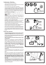
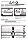
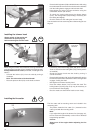
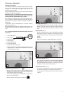
The position of the mounting plate (C/1) will depend on the
type of cutting tool in use (trimmer head or metal blade).
The position of the mounting plate determines whether the
guard will be positioned higher or lower.
When using a trimmer (line) head apply the mounting position
as shown in fig. A.
The mounting position as shown in fig. B is required for use
with the following tools:
• Star blade
• 8-tooth eddy blade
• Steel bush cutter
Always fix the metal cutter guard if a chisel type saw blade
is used (refer to page 13).
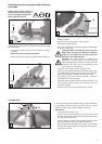
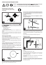
D
- To install, lay the guard on the holder on the gear box.
Place the mounting plate (D/2) on the guard in the
appropriate position (A or B) for the type of cutting tool in
use and tighten the installing screws with the Allen key as
shown.
2
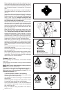
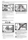
When using the blade cutting tools mentioned on the preced-
ing page, install the cutter guard with the mounting plate in
position B (see “Installing the cutter guard”).
- Unscrew the locknut (E/3) from the shaft by turning it
clockwise.
Note: The locknut is provided with a left-hand thread!
- Remove the pressure disk (E/4) and the locking disk (E/5).
- Tighten the winding guard (E/6) with the three screws
provided.
- Put the locking disk (E/5) back on (make sure it is in the
right position).
E
3
4
5
6
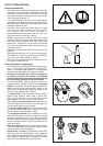
CAUTION:
The cutter guard supplied must always be fitted in the right position, to ensure your personal safety and to meet legal
accident prevention regulations.
Never use the brushcutter without a cutter guard installed!
C
B
A
1
STOP
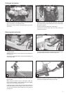
Installing the steel bush cutter, 8-tooth eddy
blade or star blade
Always switch off the engine and disconnect the spark
plug cap before mounting cutting tools! Wear protective
gloves!
F
3
7
8
4
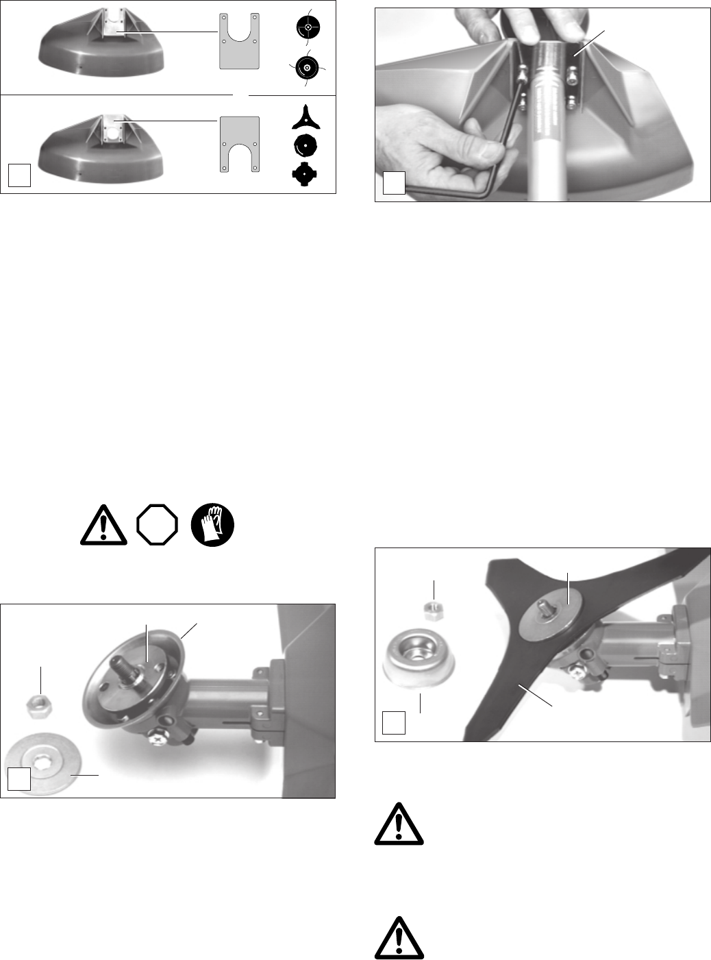
- Put on the cutting tool (F/8) and finally the pressure disk
(F/4) as shown in the picture.
Important! The picture shows the steel bush
cutter. When installing the 8-tooth eddy blade
make sure to observe the direction of rotation
arrows on blade and on cutter guard!
- Put on the sliding cup (F/7) and screw the lock nut (F/3)
manually onto the shaft.
The sliding cup is included in the accessories!
Important! The locknut (F/3) has a plastic insert
protection. For safety reasons, this nut must be
replaced immediately if it becomes loose. It must be
replaced in any event after 10 tool changes at the
latest. (Order no. 385 228 041)