


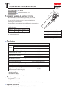
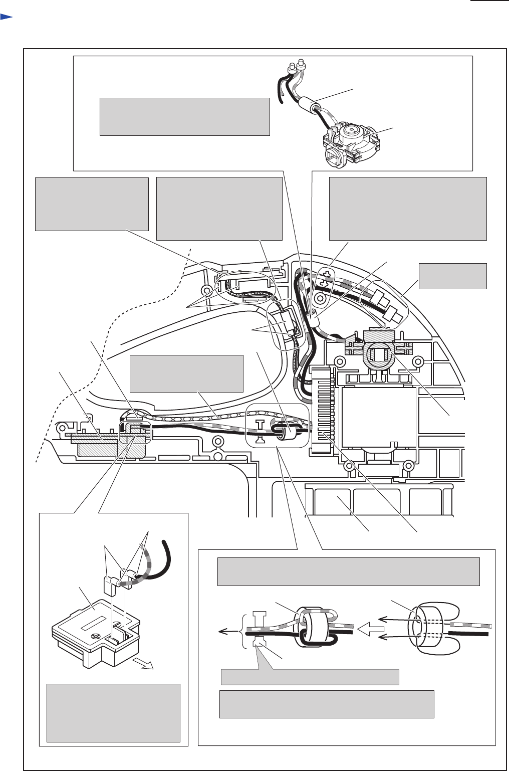
Wiring diagram in Housing set (L)
P 5/ 5
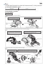
Guide Switch units’s Lead
wires between Ribs
carefully not to put them
on the Ribs.
Put Insulated
connectors here.
Fix the following Lead wires with
these Lead wire holders.
* Endbell’s Lead wires (black, red)
* Controller’s Lad wires (black, red)
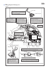
Endbell
complete
Line filter
Line filter
Line Filter
Pass Line filter’s Lead wires (black, red)
through Line filter, and then put the Line
filter as illustrated below.
Connector
Put Connectors to the position
illustrated below, and fix
the Lead wires of Switch unit
and Controller with Lead wire
holders.
Do not pass Controller’s
lead wire (yellow) between
Rib and Terminal.
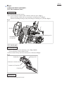
Line filter
Line filter
Passing Controller’s Lead wires (black, red) through Line filter,
coil them one time to Line filter as illustrated below.
Terminal
Rib
Rib
Fix the Lead wires with Lead wire holder.
to
Terminal
Fan 95
Controller
Yoke unit
Lead Wire Holder
In case of the specifications without Line filter,
no need to fix the lead wires with Lead wire holder.
The Flag connector has to be
connected so that its wire
connecting portion faces
Motor section side (front side).
Flag connector
Wire connecting portion
Terminal
Motor section side
Endbell Complete
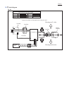
Fig. D-2