


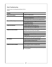
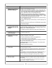


Solution
a. On PTO drive units, check coupler between engine and pump.
Tighten if necessary.
b. With pump operating, clean hose leading to control box gauge by
using ball valve located on remote magnet mount.
c. Check gauge protector to see that it is filled with oil to within 1/8” of
top of threaded hole.
d. Swap agitation gauge and control box gauge to check for faulty
gauge.
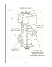
e. Inspect electric solenoid valves to see that they are opening and
closing properly. Solenoid valves require 12 volts to open properly.
Valves may need cleaning, adjustment, repair kit or new coil. Low
voltage or a weak battery will result in valves not opening com-
pletely.
a. Check that manual pressure control valve is open.
b. Turn sprayer and engine off, hold the pressure adjust switch and
listen at the electric pressure control valve for whirring sound which
indicates that the motor is turning the valve.
c. With the engine running, visually inspect the nozzles to see if the
pressure is changing. If pressure is changing, clean hose leading
to control box gauge by using ball valve located on remote magnet
mount. If problem persists, swap agitation gauge and control box
gauge to check for faulty gauge.
d. If whirring sound is not heard, check electrical connections and fuse
in the control box.
e. If fuse is good, check with 12 volt tester to see fi pressure adjust
switch is receiving current from fused wire and sending signal to the
electric pressure control valve. Replace switch if faulty.
f. If current is good, check with 12 volt tester to see if pressure adjsut
switch is receiving current from fused wire and sending signal to the
electric pressure control valve. Replace valve if faulty.
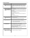
a. Check electric pressure control valve operation as follows: With unit
spraying, hold the pressure adjust switch up. The pressure on the
control box gauge should increase to a maximum pressure, remain
high for about 10 seconds and then drop to minimum pressure.
Check wire connections, valve operation and voltage to switch and
valve. Replace valve if necessary.
b. Tank agitation may be restricted. Check that agitation valve is
open and agitator head has four jet streams shooting out.
c. Relieve excess pressure on electric pressure control valve. Open
electric pressure control valve to maximum pressure, then close the
manual control valve unit control gauge reads 15-20 psi above de-
sired nozzle pressure.
a. Check application guide for flow rate and catch nozzle flow to deter-
mine pressure drop.
b. Swap agitation gauge and control box gauge to check for faulty
gauge.
c. Check for clogged or pinched boom feed lines from solenoids.
d. Inspect electric solenoid valves to see that they are opening and
closing properly (Page 19). Solenoid valves require 12 volts to
open properly.
Valves may need cleaning, adjustment, repair kit or a new coil.
Low voltage or a weak battery will result in valves not opening com-
pletely.
Problem
4. Agitation gauge registers
pressure but control box
gauge reads zero or is very
sluggish after nozzles are
turned off.
5. Moving the pressure adjust
switch on the control box does
not change nozzle pressure
but both gauges show some
pressure.
6. Nozzle pressure cannot be
reduced below 20-30 psi.
7. During calibration control
box gauge reads about 30 psi.
Nozzles are spraying about 10
psi. When catching flow of
nozzles, there is a large pres-
sure drop.
29