


General Notes for Field Operation
1. Lubricate the sprayer as needed. Refer to “
Maintenance and Lubrication” section start-
ing on page 24.
2. When transporting the sprayer, do not exceed
20 mph and do not unnecessarily transport with
chemical in the tank. Fasten the level-float pin
in the lock position (if applicable) before folding
the boom and transporting it.
3. Make sure all tank shut off valves (except the
tank drain) are opened.
4. Calibrate sprayer with water only. Calibrate
with the sprayer tank half full of water. Refer to
Tee Jet Manual.
5. Adjust throttling valves on the solenoids and
the manual pressure adjustment valve.
6. Inspect and clean, if necessary, pump nozzles
and filter.
7. Make sure the material you wish to apply can
be used in your sprayer without causing dam-
age to the pump seal.
IMPORTANT
The Hy Pro pump supplied with your sprayer is not
designed for use with every application. Materials
containing solvents, paints or solutions containing
abrasives will damage the pump. If you are unsure
of your chemicals, consult your dealer for suitability
or your application.
8. Safely and carefully add the chemical to the
sprayer tank. Always wear protective equip-
ment when handling chemicals. See Personal
Safety Equipment in “Important Safety Infor-
mation” section starting on page 5. By low,
chemical containers must be rinsed three
times. The container should then be punctured
to prevent future use. An alternative is to jet-
rinse or pressure rinse the container. Follow
chemical manufacturer’s recommendations for
safe handling of chemicals.
9. Check the sprayer initially and periodically for
loose bolts, pins and hose clamps. Check the
hoses, pumps, valves and fittings for leaks.
10. Make sure that the hand wash tank is full of
clean water.
Preparing the Sprayer
NOTE
Refer to Plumbing Diagram on page 13 if you need
help identifying specific sprayer components.
1. Close drain valve, air clean out valve and filter
clean out valve.
2. Open tank and inspect interior for contaminating
materials.
3. If the sprayer is equipped with a pump drive en-
gine (in addition to the vehicle’s engine), check
fuel and oil levels.
4. Perform an electrical system check on the boom
solenoids and pressure control switch. The sole-
noid switches will emit an audible click when the
switch is opened or closed. The pressure control
valve will make noise when the pressure control
adjustment switch is engaged. If any part fails,
refer to “Troubleshooting” section starting on page
26. Turn all switches off when finished with this
step.
5. Open the pump suction valve.
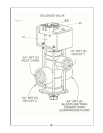
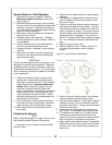
6. Open the agitation valve. Refer to Figure 5-1 if
you are not sure whether a valve is open or
closed.
Figure 5-1 Valve Position Identification
7. Open the manual pressure control valve located
next to the electric pressure control valve.
8. Extend the boom sections. Check with the Boom
Operator’s manual if you are unfamiliar with the
operation of the boom. If using a level float boom,
remove the locking pin.
9. Some booms are equipped with a ball valve at
each nozzle. If so equipped, open these valves.
10. To operate the turf boom at a 15’ width, fold the
outer sections of the boom and close the ball
valves in front of the nozzles in the outer sections.
Note: this option is not present on all booms.
11. Attach water hose to the anti-siphon fill assembly.
Make sure the knife valve is open and fill the tank
at least 1/3 full, more if performing complete sys-
tems check.
21