12. Start the vehicle’s engine (and pump engine if so
equipped), turn the master switch on (turning on the
pump) and set the throttle to maintain a minimum of
50 PSI on the agitation gauge. If agitation pressure
does not rise immediately, prime the pump by bleed-
ing air through the air clean out valve. Open the air
clean out valve and insert sharp object on the air
valve core to let air escape for ten seconds or until
water is seen at the valve. Close the air clean out
valve. An alternative method is to slightly open the
filter clean out valve, closing it once water is seen at
the valve.
13. Visually inspect hoses and all connections for leaks.
14. Refer to Tee Jet manual to determine pressure and
speed for desired chemical application rates.
15. Turn the boom section switches on and adjust the
manual pressure control valve to 10-20 PSI above
the desired operating pressure. This reduces the
sensitivity of the electric pressure control valve and
allows more precise adjustment from the control
box.
16. Calibrate throttling valves as described in the next
section. Calibration is not necessary every time the
sprayer is used but must be performed after chemi-
cal changes and to ensure the system is operating
properly. It does not harm the system to recalibrate
the throttling valves each time the sprayer is used.
17. Remove the nozzles from the check valve bodies
and flush the boom feed lines briefly by turning the
boom sections on. This will remove any debris that
may accumulate in the feed lines. Turn the boom
sections off, inspect the check valves and dia-
phragms and replace the nozzles.
18. Visually inspect nozzle spray patterns for streaking
or plugged nozzles. Clean or replace worn or dam-
aged nozzles as needed. Set the nozzle angle at 20
degrees rearward.
Calibrating The Throttling Valves
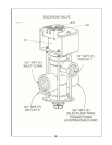
Refer to Figure 5-2:
1. Start by closing all three gray throttling valves by
loosening the jam nut and tightening the knobs all
the way down and then backing off each knob one
complete turn. Do not use excessive pressure.
2. Start the engine and turn the master switch on.
3. Turn on all three boom section switches at the con-
trol box.
4. Adjust the pressure adjust switch on the control bow
until the nozzle pressure measures 20 PSI as indi-
cated on the large gauge at the control box.
5. Turn the left boom section off. Leave the other two
sections on. This will cause the boom pressure to
increase at the other town boom sections.
6. Adjust the gray knob on the left throttling valve until
the pressure again measures 20 PSI on the large
gauge. Firmly lock the gray jam nut against the
knob to hold the knob’s position.
7. Turn the left boom section on and off several times.
If the pressure does not stay at 20 PSI, readjust the
gray knob.
8. When finished with the left boom section, proceed to
the center boom section. Turn the left boom section
on, the center boom section off and the right boom
section on. Adjust the center throttling valve in the
same manner as the one just completed.
9. When finished with the center boom section, adjust
the right boom section. Turn the right section off,
the center and left boom sections on and calibrate
the gray valve in the same manner.
All three throttling valves are now set to maintain
constant boom pressure regardless of which boom
sections are turned on.
When spraying at high gallon rates or extremely viscous
spray solutions you may see the pressure rise when all
three seciton s of the boom are turned off. This condi-
tion is caused by too much fluid trying to bypass back to
the tank agitation. As long as the boom pressure re-
turns to the desired gauge pressure when one or more
boom sections are on, there are no adverse effects on
spraying accuracy.
Adding the Chemicals
NOTE
These procedures are general guidelines for mixing
chemicals. Carefully follow the manufacturer’s instruc-
tions and use these steps in addition when applicable.
IMPORTANT
If you have not calibrated your sprayer, do so before
starting this section.
1. If using a wettable powder, make a slurry in a sepa-
rate container by adding water to the chemical, in
accordance with the manufacturer’s instructions.
22


