


4
NOTE: DIAGRAMS & ILLUSTRATIONS ARE NOT TO SCALE.
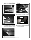
Step 3. Insert snap switch bracket mounting tabs between the pedestal
and the firebox bottom. See Figure 17.
Figure 16
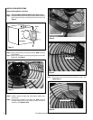
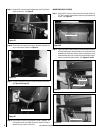
Step 2. Insert a large flat head screwdriver or pry bar into the small open-
ing between the pedestal mounting flange and the bottom firebox
of the stove. Use the large screwdriver or pry bar to increase
the opening size between the firebox bottom and pedestal. See
Figure 16 - This increased opening between the pedestal and
bottom firebox will be needed to insert the snap switch bracket
mounting tabs.
Firebox
Pedestal Mounting Flange
WOODSTOVES WITH PEDESTAL BASE
Leg based units, see instructions on Page 6.
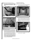
Step 1. From rear of stove, using a 9/16” wrench or socket, loosen both
left and right pedestal mounting bolts but do not fully remove
the bolts from threaded holes as shown in Figure 15.
Figure 15
Back View of Pedestal
Bolts
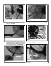
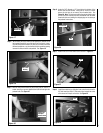
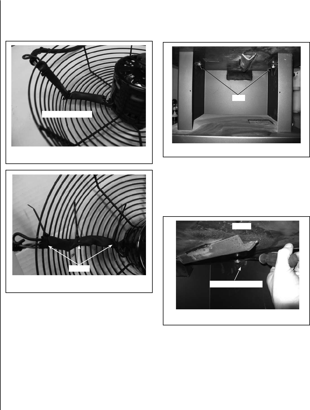
Step 12. Shrink the tube with heat (heat gun, hair dryer, etc.)
Step 13.
Secure wires in the heat shrink tube to the fan cage using (3)
wire ties making sure wires/heat shrink tube follow contour of
inner side of blower cage. Cut off the excess wire tie. NOTE*
BE SURE WIRES ARE CLEAR OF FAN BLADE!!! See Figures
13 and 14.
Step 14.
Reinstall the blower fan blade.
Step 15.
Reinstall the blower assembly as shown in Figure 2 and the
following instructions; Ensure the wiring harness on the blower
cage is at the bottom right when mounted to the back heat shield
of the stove. Be aware that the blower wiring harness should
be clear of the back of the firebox and blower fan blades. The
blower can now be fastened to the back of the heat shield with
the four screws and washers that were removed earlier in this
step using the 5/32” allen wrench/T-handle. Visually inspect
that the blower is centered in large opening on the back of the
heatshield. If not centered in the opening the fan blades could
make contact with the heatshield making excessive noise. Once
everything is correctly in place you can then tighten down all
four screws. Tighten the screws moderately tight but do not
over tighten as you may strip the holes out.
Figure 13
Figure 14
Wires / Heat Shrink Tube
Wire Ties