3
NOTE: DIAGRAMS & ILLUSTRATIONS ARE NOT TO SCALE.
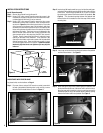
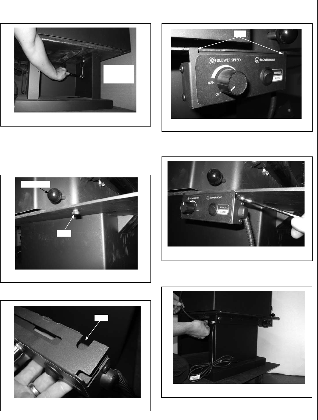
Step 5. With the snap switch bracket in place, using a 9/16” wrench or
socket wrench you can now tighten down both left and right side
pedestal bolts. See Figure 7.
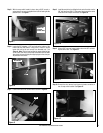
Step 6. Locate the 3/8” diameter x 1/2” long bolt on the bottom of the
firebox near the draft handle. Using a 9/16” wrench or socket
loosen this bolt but do not remove from threaded hole. See
Figure 8. Note: This bolt was holding the stoves shipping legs
on the stove and should have been reinstalled with the other
three bolts that were holding the shipping legs on the stove per
the pedestal instructions.
Step 7. Locate front slot on the Control Box as shown in Figure 9.
Step 8. Install the control box by sliding the front control box slot over the
3/8” bolt head from Step 6. Slide control box towards the center
of the stove until it stops on the tabs. See Figure 10.
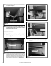
Step 9. Using a 9/16” open end wrench tighten down the 3/8” bolt hold-
ing the control box. See Figure 11.
Step 10. Connect the wire harness from blower to female connector on
rear of snap switch bracket. See Figure 12.
Figure 7
Figure 8
Figure 9
Figure 10
Figure 11
Figure 12
Bolt
Draft Handle
Tighten Left
and Right
Pedestal Bolts
Slot
Tabs


