


2
NOTE: DIAGRAMS & ILLUSTRATIONS ARE NOT TO SCALE.
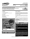
Figure 2
WOODSTOVES WITH PEDESTAL BASE
Leg based units, see instructions on Page 4.
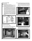
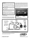
Step 1. From rear of stove, using a 9/16” wrench or socket, loosen both
left and right pedestal mounting bolts but do not fully remove
the bolts from threaded holes as shown in Figure 3.
Stove Back
Blower
INSTALLATION INSTRUCTIONS
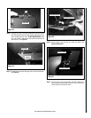
Install Blower Assembly
Step 1. Remove the contents from the blower kit.
Step 2. Using a 5/32” allen wrench/T-handle remove the screws in the
round knock-out plate on the back of the stove. Bend the knock-
out plate back and forth until it can be removed.
Step 3. Using a 5/32” allen wrench/T-handle, remove the four screws
and washers from the back of the stove. Next, mount the blower
as shown in Figure 2 and the following instructions; Ensure the
wiring harness on the blower cage is at the bottom right when
mounted to the back heat shield of the stove. Be aware that the
blower wiring harness should be clear of the back of the firebox
and blower fan blades. The blower can now be fastened to the
back of the heat shield with the four screws and washers that
were removed earlier in this step using the 5/32” allen wrench/
T-handle. Visually inspect that the blower is centered in large
opening on the back of the heatshield. If not centered in the
opening the fan blades could make contact with the heatshield
making excessive noise. Once everything is correctly in place
you can then tighten down all four screws. Tighten the screws
moderately tight but do not over tighten as you may strip the
holes out.
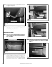
Step 4. While holding the snap switch bracket against the pedestal, slide
the bracket towards the rear of the stove until it comes to a stop.
Once the snap switch bracket is in place you can then remove the
flat head screwdriver or pry bar that was used to create the opening
between the firebox bottom and pedestal. See Figure 6.
Step 3. Insert snap switch bracket mounting tabs between the pedestal
and the firebox bottom. See Figure 5.
Figure 3
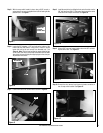
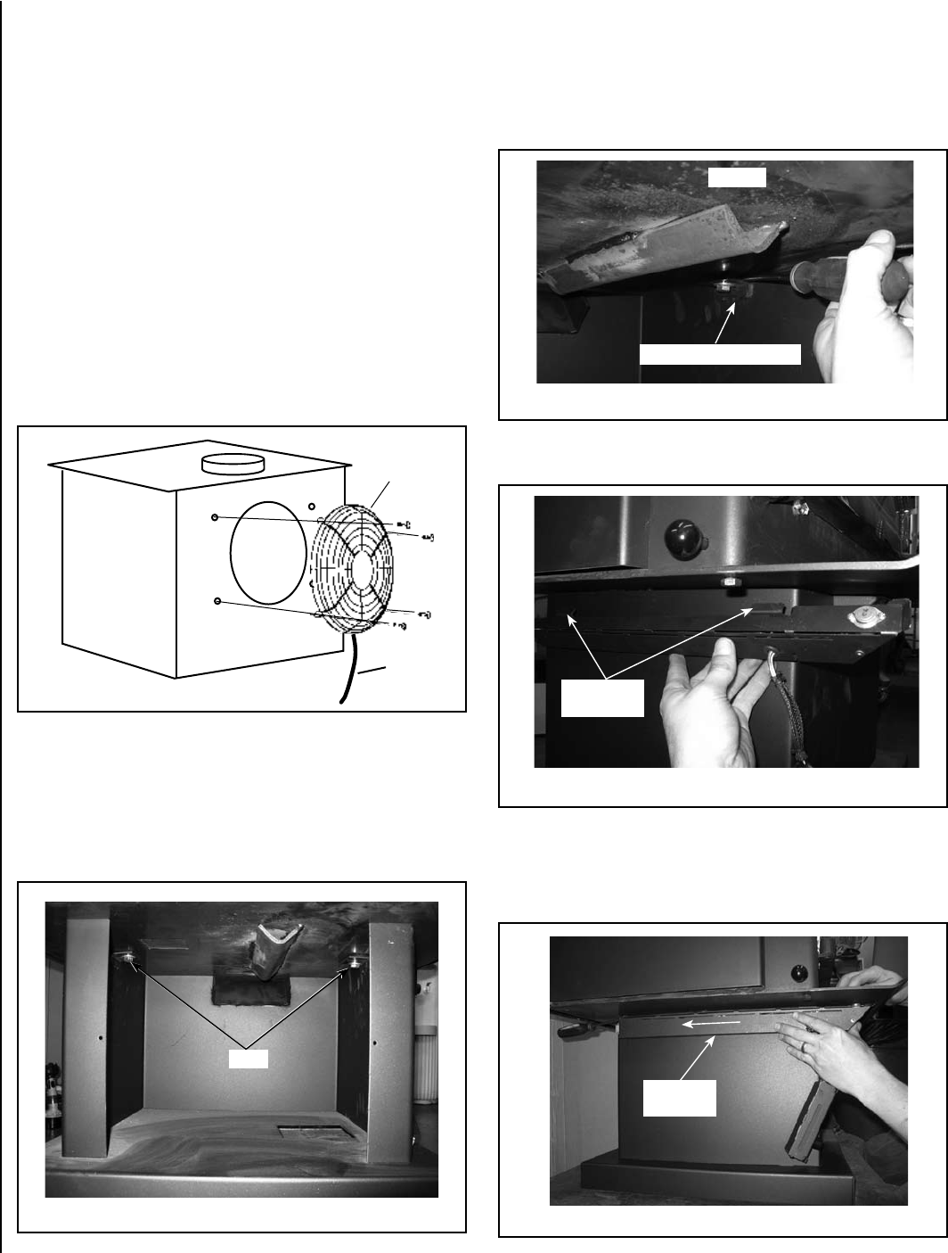
Figure 4
Figure 5
Figure 6
Back View of Pedestal
Step 2. Insert a large flat head screwdriver or pry bar into the small open-
ing between the pedestal mounting flange and the bottom firebox
of the stove. Use the large screwdriver or pry bar to increase
the opening size between the firebox bottom and pedestal. See
Figure 4 - This increased opening between the pedestal and
bottom firebox will be needed to insert the snap switch bracket
mounting tabs.
Firebox
Pedestal Mounting Flange
Snap switch
Bracket Tabs
Snap switch
Housing
Bolts
Wire
Harness