21
Section 4: Adjustments
10/08/14
SB1051, SB1064, SB1574, & SB2584 with S/N 881640- Snow Blowers 370-027M
Table of Contents
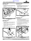
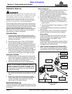
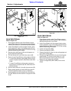
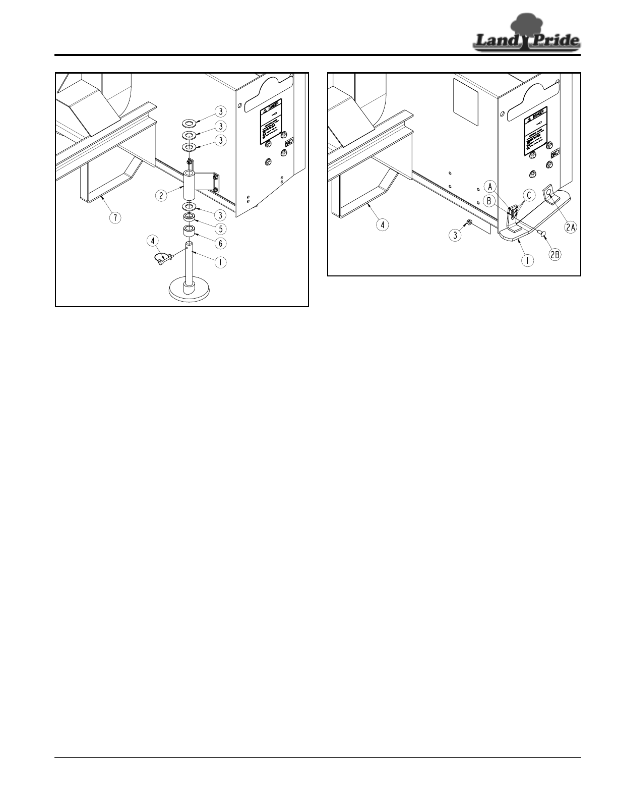
Inner Skid Shoe Assembly
Figure 4-5
Inner Skid Shoes
Refer to Figure 4-5:
1. Place support blocks under Snow Blower support
rests (#7) to hold unit off the ground high enough to
remove skid shoes (#1) from skid shoe mounts (#2).
2. Lower Snow Blower onto the support blocks, place
tractor gearshift in park, shut tractor engine off and
remove switch key. Make certain PTO is not running
before dismounting from tractor.
3. Remove wire retaining pin (#4) and all spacers on
top of skid shoe mount (#2).
4. Pull skid shoes (#1) out of skid shoe mount (#2).
5. Raise or lower Snow Blower cutting edge as follows:
• To raise Snow Blower cutting edge, add an equal
amount of spacers (#3, #5, and/or #6) to both skid
shoes.
• To lower Snow Blower cutting edge, remove an
equal amount of spacers (#3, #5, and/or #6) from
both skid shoes.
6. Reinsert skid shoes (#1) into skid shoe mounts (#2).
7. Store unused spacers on top of skid shoe mounts.
(Three #3 spacers shown on top in illustration)
8. Secure spacers and skid shoes with wire retaining
pin (#4). Make sure wire retainer is caught over end
of pin.
33286
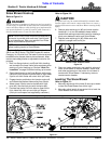
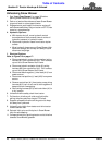
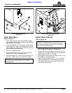
Outer Skid Shoe Assembly
Figure 4-6
Outer Skid Shoes
Refer to Figure 4-6:
1. Place support blocks under Snow Blower support
rests (#4) to hold unit off the ground high enough to
adjust skid shoes (#1) up or down.
2. Lower Snow Blower onto the support blocks, place
tractor gearshift in park, shut tractor engine off, and
remove switch key. Make certain PTO is not running
before dismounting from tractor.
3. Loosen carriage bolt (#2A).
4. Remove carriage bolt (#2B).
5. Rotate skid shoe (#1) down to raise cutting edge and
up to lower cutting edge.
6. Reinsert carriage bolt (#2A) into one of 5 skid shoe
square holes “C” and one of two holes “A” or “B”
behind the skid shoe mounting tab. Secure skid
shoes with hex flange lock nuts (#3).
7. Tighten carriage bolts (#2A & #2B) to the correct
torque.
33287


