


9
Section 2: Optional Assembly & Set-up
10/08/14
SB1051, SB1064, SB1574, & SB2584 with S/N 881640- Snow Blowers 370-027M
Table of Contents
Section 2: Optional Assembly & Set-up
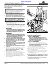
SB1064, SB1574, & SB2584
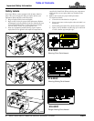
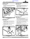
Chute Rotation Powered By Manual Drive
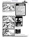
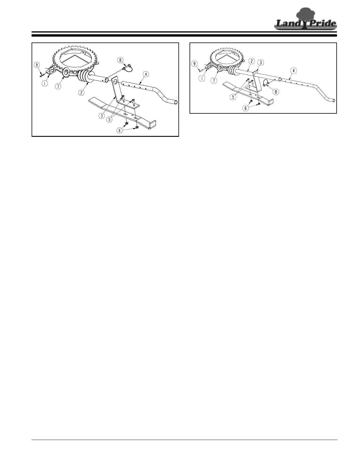
Figure 2-2
Chute Rotation, Manual
For SB1064, SB1574, & SB2584 Models
The following instructions are for Snow Blower model
numbers SB1064, SB1574, and SB2584 only.
Refer to Figure 2-2:
1. Slide 1 1/4" SAE flat washer (#7) onto spiral end of
chute adjustment tube (#2).
2. Insert spiral end of chute adjustment tube (#2)
through hole in mounting bracket (#1) as shown.
3. Insert opposite end of chute adjustment tube (#2)
into hole in chute adjustment mount (#3).
4. Attach adjustment mount (#3) to Snow Blower
mainframe as shown with two 3/8"-16 x 1 1/4" GR5
cap screws (#5) and hex flange lock nuts (#6).
Tighten lock nut to the correct torque.
5. Drive 1/4" x 1 1/2" roll pin (#9) through holes in spiral
end of chute adjustment tube (#2) until both ends of
the roll pin extends equally through both holes in
adjustment tube.
6. Insert rotation handle (#4) into chute adjustment
tube (#2) and secure with wire retaining pin (#8).
Make certain retaining wire is caught over end of pin
to keep pin from falling out.
33237
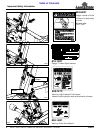
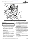
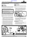
SB1051 Chute Rotation Powered By Manual Drive
Figure 2-1
Chute Rotation, Manual
For SB1051 Model
The following instructions are for Snow Blower model
number SB1051 only.
Refer to Figure 2-1:
1. Slide 1 1/4" SAE flat washer (#7) onto spiral end of
chute adjustment tube (#2).
2. Insert spiral end of chute adjustment tube (#2)
through hole in mounting bracket (#1) as shown.
3. Insert opposite end of chute adjustment tube (#2)
into hole in chute adjustment mount (#3).
4. Attach adjustment mount (#3) to Snow Blower
mainframe as shown with two 3/8"-16 x 1 1/4" GR5
cap screws (#5) and hex flange lock nuts (#6).
Tighten lock nut to the correct torque.
5. Drive 1/4" x 1 1/2" roll pin (#9) through holes in spiral
end of chute adjustment tube (#2) until both ends of
the roll pin extends equally through both holes in
adjustment tube.
6. Insert rotation handle (#4) into chute adjustment
tube (#2) and secure with wire retaining pin (#8).
Make certain retaining wire is caught over end of pin
to keep pin from falling out.
33238