


18
RTA10 & RTA15 Series Rotary Tillers 311-252M
5/05/06
Land Pride
Section 4 Maintenance and Lubrication
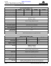
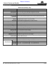
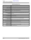
Table of Contents
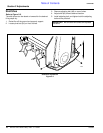
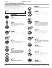
4. Inspect the clutch and ensure that the scribed
markings made on the clutch plates have changed
position. Slippage has not occurred if any two marks
on the friction disk and plate are still aligned. A clutch
that has not slipped must be disassembled to
separate the friction disk plates. See Clutch
Disassembly & Reassembly on page 19.
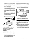
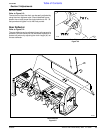
Refer to Figure 4-3 (View - B):
5. Turn all 4 nuts fully back if no two marks on the friction
disk and plate are still aligned. Clutch is ready for use.
6. The clutch should be checked during the first hour of
cutting and periodically each week. An additional set
of scribe marks can be added to check for slippage.
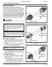
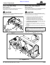
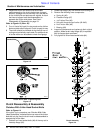
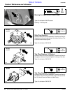
Clutch Run-In With 8- Hex Head Socket Bolts
Figure 4-2
Clutch Run-In With 4 Tightening Nuts
Figure 4-3
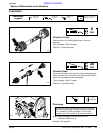
Clutch Disassembly & Reassembly
Clutches With 8-Hex Head Socket Bolts
Refer to Figure 4-4
If the clutch run-in procedure, see Clutches With 8-Hex
Head Socket Bolts, indicated that one or more of the friction
disks did not slip, then the clutch must be disassembled to
separate the friction disks.
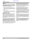
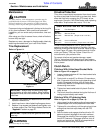
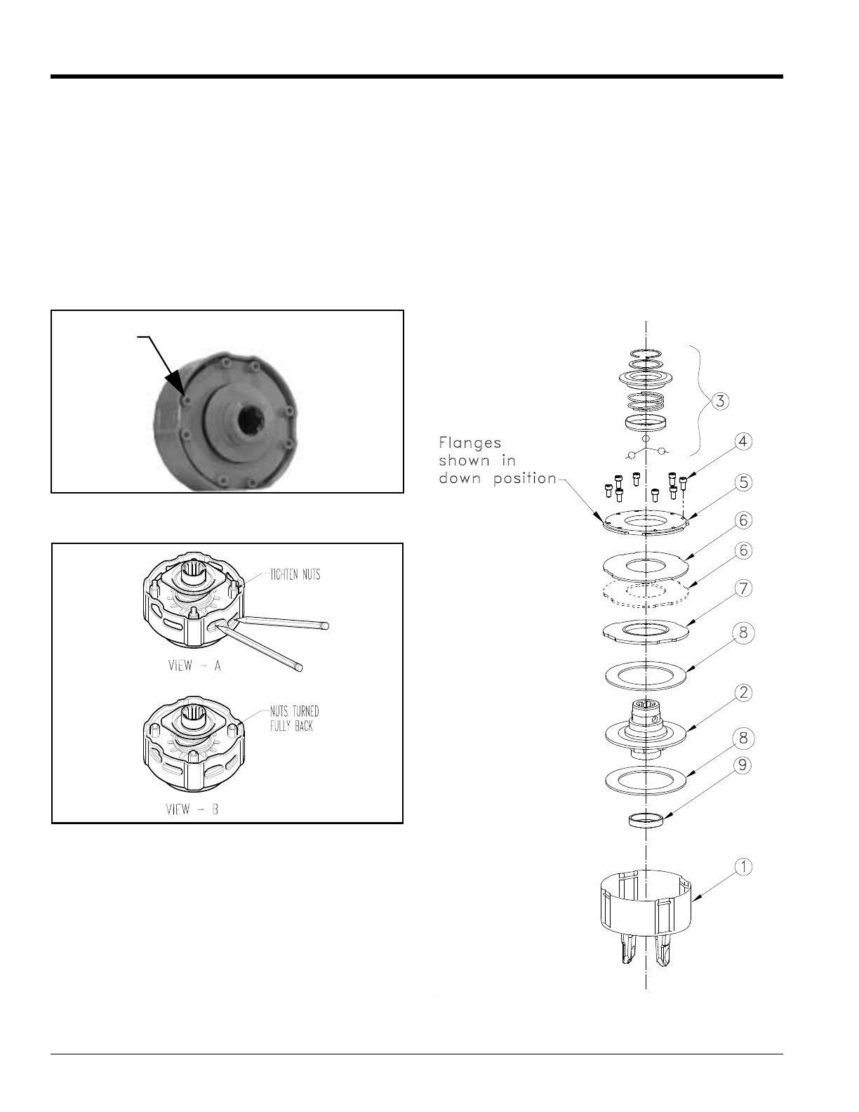
1. Rotate 8 hex head socket bolts (#4) all the way out to
free stop flange (#5).
2. Rotate stop flange (#5) and remove from housing (#1)
3. Remove the following inner components:
a. Spring kit (#6)
b. Pressure flange (#7)
c. 1st Friction Disc (#8)
d. Hub with flange and pull collar (#2 & #3)
e. 2nd Friction disc (#8)
f. Bearing (#9)
4. Inspect all components and replace to their original
position. Make certain stop flange (#5) is replaced
with its flanges down as shown.
5. Fully tighten all 8 hex head socket bolts (#4).
Clutch Assembly
Figure 4-4
Hex Head
Socket Bolts
21270
22171
21302