


9
5/05/06
RTA10 & RTA15 Series Rotary Tillers 311-252M
Land Pride
Section 1 Assembly and Set-Up
Table of Contents
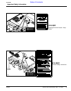
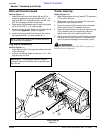
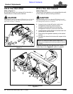
Hitch and Driveline Guard
Refer to Figure 1-1:
1. Install both top 3-point hitch plates (#6 and #7) to
outside of gearbox mounting frame with 5/8” x 1 1/2”
long bolts (#3), 5/8” lockwashers (#4), and 5/8” nuts
(#5). Do not tighten hardware at this time.
2. Install spacer (#9) between upper 3-point hitch plates
(#6 & #7) with 5/8” x 3 1/2” long bolt (#8).
3. Securely tighten all bolts. Refer to the Torque Values
Chart in the “Appendix” section on page 27.
4. Install driveline guard (#10) to the top of the 3-point
hitch plates with four 1/4” wing screws (#11).
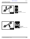
Leg Stand Assembly
Refer to Figure 1-1:
1. Insert leg stand (#13) into leg stand holder on the end
of the tiller frame.
2. Adjust to the desired height and pin with 1/4” x 1 3/4”
long wire lock pin (#14).
NOTE: Remove driveline guard for easier access to
the driveline at the gearbox.
IMPORTANT: The three upper holes are used for
parking the tiller and the bottom hole is used when the
tiller is in use.
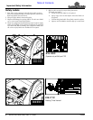
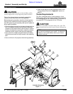
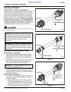
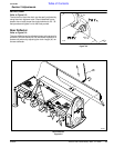
Tractor Hook-Up
Refer to Figure 1-2:
1. When using tractors with multi-speed PTO, be certain
PTO is set for 540 rpm.
2. Back tractor up to tiller until lower 3-Point links are
aligned with hitch clevises on tiller.
3. Secure the tractor’s 3-Point lower links to the lower
hitch clevises using 7/8" diameter hitch pins.
4. Secure the tractor’s top link to the tiller top hitch using
a 3/4" diameter hitch pin (supplied by customer).
Adjust tractor top link in order to level the tiller.
5. Adjust the tractor’s 3-Point hitch lift height so that the
tiller tines are not lifted more than 14 inches off the
ground to prevent damage to the driveline u-joints.
!
WARNING
Lifting unit more than 14” high while PTO is engaged may
damage driveline components.
Tractor Hook-Up
Figure 1-2
10134
22191