


11
5/05/06
RTA10 & RTA15 Series Rotary Tillers 311-252M
Land Pride
Section 1 Assembly and Set-Up
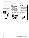
Table of Contents
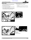
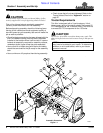
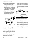
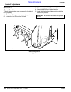
b. Pull driveline apart into two sections as shown in
Figure 1-6. Attach the outer driveline universal
joint to the tractor shaft and inner driveline
universal joint to the tiller gearbox shaft. Pull on
each driveline section to be sure the universal
joints are secured to the shafts.
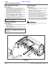
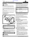
c. Hold driveline sections parallel to each other to
determine if they are too long. The inner and outer
shields on each section should end approximately
1" short of reaching the universal joint shield on
the adjacent section (see “B” dimension). If they
are too long, measure 1" (“B” dimension) back
from the universal joint shield and make a mark at
this location on the inner and outer driveline
shields.
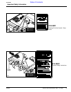
d. Cut off inner shield at the mark (“X” dimension).
Cut the same amount off the inner shaft (“X1”
dimension). Repeat cut off procedure (“Y”&“Y1”
dimensions) to the outer driveline half.
e. Remove all burrs and cuttings.
Shortening the driveline
Figure 1-6
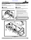
Checking Driveline Maximum Length
Make sure you have gone through the steps in
"Checking Driveline Minimum Length" on page 10
before checking maximum length.
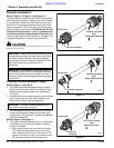
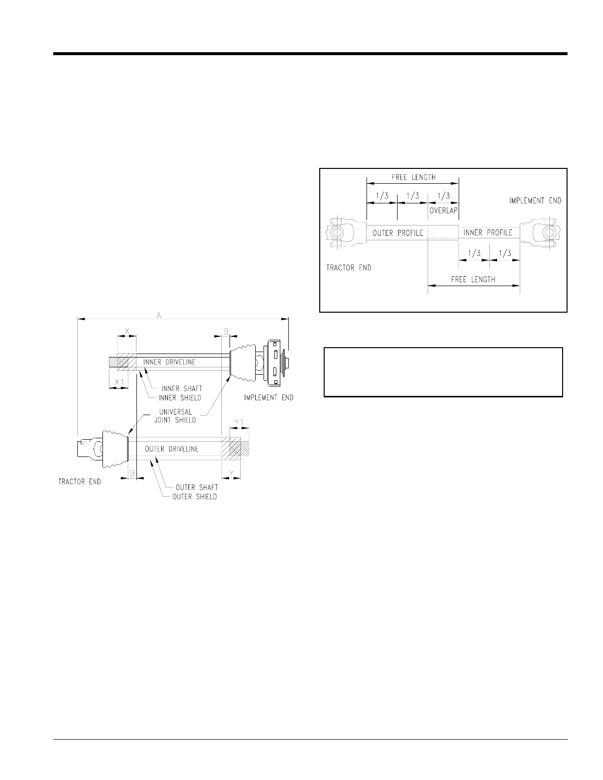
Refer to Figure 1-7
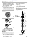
The driveline maximum length must, when fully
extended, have a minimum overlap of the profile tubes by
not less than 1/3 the free length with both inner and outer
profile tubes being of equal length.
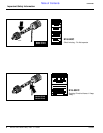
1. Apply multi-purpose grease to the inside of the outer
shaft and reassemble the driveline.
2. Assemble the two driveline profiles together with just
1/3 overlapping of the profile tubes as shown in Figure
1-7. Measure and record this overall length for
checking driveline length in step 9 below.
13588
3. Attach inner driveline yoke end to the tiller gearbox
input shaft.
4. Attach outer driveline yoke end to the tractor's PTO
shaft.
5. The driveline should now be moved back and forth to
insure that both ends are secured to the tractor and
Rotary Tiller PTO shafts. Reattach any end that is
loose.
Driveline Maximum Length
Figure 1-7
6. Hook driveline safety chain in the hole in the inner
driveline guard. Attach the other end to the tiller’smain
frame.
7. Start tractor and raise tiller just enough to remove
blocks used to support the tiller frame in step 3a on
page 10.
8. Slowly engage tractor’s hydraulic 3-point to lower the
Rotary Tiller. Check for sufficient drawbar clearance.
Move drawbar ahead, aside or remove if required.
9. Raise and lower implement to find maximum
extended driveline length. Check to make certain that
the driveline overall length does not extend beyond
the maximum recorded length in step 2.
24513
Outer Shielding has been removd for clarity.
IMPORTANT: A small chain is supplied with the
driveline. This chain must be attached to the inner
driveline shield and to the tiller to restrict shield
rotation.