


10
Section 1: Assembly and Set-Up
RCR1860 and RCR1872 Series Rotary Cutters 312-849M
12/17/07
Land Pride
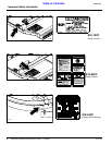
Table of Contents
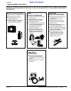
Driveline Installation
If the Rotary Cutter is to be used on more than one
tractor, an additional driveline may be required
especially if a quick hitch is used.
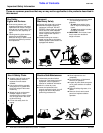
!
CAUTION
Do not use a PTO adaptor. A PTO adapter will increase strain
on the tractor’s PTO shaft resulting in possible damage to the
shaft and driveline.
!
CAUTION
Tractor PTO shield and all Rotary Cutter guards must be in
place at all times during operation!
!
CAUTION
Always engage parking brake, shut off tractor and remove key
before dismounting from tractor.
!
WARNING
Damaged drivelines can cause serious injury or death.
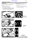
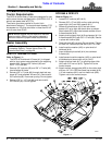
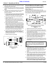
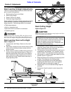
Maximum PTO Driveline Movement During Operation
Figure 1-4
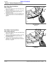
Driveline Minimum Length
IMPORTANT: The driveline must be lubricated
before putting it into service. Refer to “Lubrication”
on page 22.
IMPORTANT: Some tractors are equipped with
multispeed PTO ranges. Be certain your tractor ‘s
PTO is set for 540 rpm.
IMPORTANT: Avoid premature driveline
breakdown. A driveline that is operating must not
exceed an angle of 25 degrees up or down while
operating the 3-point lift. See Figure 1-4 below.
24872
IMPORTANT: Always check driveline minimum
length during initial setup, when connecting to a
different tractor and when alternating between using
a quick hitch and a standard 3-point hitch. More than
one driveline may be required to fit all applications.
Refer to Figure 1-6 on page 11:
1. Obtain the shortest distance possible between
tractor PTO shaft and gearbox shaft by starting the
tractor and slowly engaging 3-point lift to move the
lower arms up or down until the gearbox shaft is
aligned and level with the tractor's PTO shaft.
Securely block cutter deck in this position.
2. Place tractor gear selector in park, shut tractor
engine off, set park brake and remove switch key.
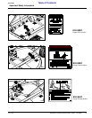
Refer to Refer to Figure 1-5:
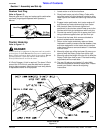
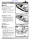
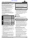
3. Remove snap ring (#1) from the 3rd link pin shipping
location. Remove rubber protective sleeve from
gearbox input shaft and install driveline as follows:
SLIP-CLUTCH DRIVELINE:
a. Discard snap ring (#1).
b. Slide slip-clutch driveline (#5) onto the gearbox
input shaft.
c. Align holes in driveline with hole in gearbox shaft
and insert 1/2” x 3 1/2” long GR8 bolt (#2). Secure
with 1/2” nut (#3) and 1/2” jam nut (#4).
d. Push and pull driveline to be sure it is securely
fastened to the gearbox shaft.
SHEAR-BOLT DRIVELINE:
a. Slide shear-bolt driveline onto gearbox shaft.
b. Install snap ring (#1) on gearbox shaft groove.
The snap ring is added security in the event the
shear-bolt should break.
c. Align holes in driveline with hole in gearbox input
shaft and insert 1/2” x 3 1/2” GR2 shearbolt (#2).
Secure with 1/2” nut (#3) and 1/2” jam nut (#4).
d. Push and pull the driveline to be sure it is securely
fastened to the gearbox shaft.
Driveline Installation with Slip-Clutch Driveline Shown
Figure 1-5
NOTE: A driveline that is too long can damage
tractor, gearbox and/or driveline. Check driveline
with gearbox shaft aligned and level with the tractor's
PTO shaft. This arrangement will provide the
shortest distance possible between the two shafts.
21408