


8
Section 1: Assembly and Set-Up
RCR1860 and RCR1872 Series Rotary Cutters 312-849M
12/17/07
Land Pride
Table of Contents
Section 1: Assembly and Set-Up
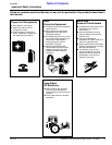
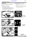
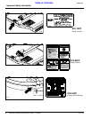
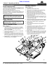
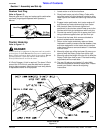
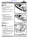
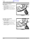
Figure 1-1
21407
RCR1860 & RCR1872
Refer to Figure 1-1:
1. Loosen 5/8” locknuts (#5 & #13).
2. Remove 5/8” x 5” bolt (#9) and lay aside pivoting
upper hitch (#10) and hitch spacer (#11).
3. Rotate A-frame braces (#12) and rear frame
braces (#7) up to align with each other as shown.
Rear braces (#7) should be located outside of front
A-frame braces (#12).
4. Attach pivoting upper hitch (#10) and spacer (#11) to
A-frame braces (#12) with 5/8” x 5” bolt (#9). Secure
in place with locknut (#8).
5. Draw lock nuts (#5) up snug. Do not tighten. Tighten
all other 5/8” locknuts (#3, #8 & #13) to 170 ft.-lbs.
6. Install machine washer (#15) on pivot shaft of
tailwheel (#14).
7. Insert tailwheel pivot shaft (#14) into tailwheel
A-frame (#1).
8. Install second machine washer (#15) on pivot shaft
of tailwheel and secure with roll pin (#16).
9. Attach driveline hook (#17) to pivoting upper hitch
(#10) with 3/8” hex nut (#19). Tighten nut to the
correct torque.
10. Attach manual storage tube (#22) to the cutter deck
with two 1/4”-20 x GR5 hex head cap screws (#18).
1/4” lock washers (#21) and hex head nuts (#20).
Tighten nuts to the correct torque.
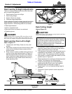
Tractor Requirements
The RCR18 Series Rotary Cutters are designed for use
with tractors that are equipped with a (540 RPM 1 3/8”-6
spline) rear power take-off (PTO).
The tractor must also provide for 3-point hitch
attachment Category I. The tractors rated drawbar PTO
horsepower on a 3-point should be no less than 20 HP
and no more than 50 HP.
Dealer Assembly
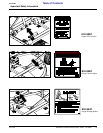
RCR1872 Tailwheel A-Frame
Refer to Figure 1-1:
1. The RCR1872 tailwheel A-Frame (#1) is shipped
with its short cross brace attached to the adjusting
bracket (#2). Remove 5/8” locknut (#3) and
5/8” x 1 1/2” bolt (#4).
2. Remove 5/8” locknuts (#5) and 5/8” x 2” bolts (#6)
from tailwheel A-frame.
3. Reinsert 5/8” x 2” bolts (#6) through deck tab, rear
brace (#7) and tailwheel A-frame (#1). Secure with
5/8” locknuts (#5). Draw nuts up snug. Do not tighten.
4. Reinsert 5/8” x 1 1/2” bolt (#4) and secure with
5/8” locknut (#3). Do not tighten.
NOTE: Ballast weights may be required to maintain
steering control. Refer to your tractor’s operator’s
manual to determine proper ballast requirements.
NOTE: Do not tighten hardware until assembly
is complete. Refer to “Torque Values Chart For
Common Bolt Sizes” on page 28.