


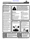

9
Section 1: Assembly and Set-Up
11/25/15
RCR1542 and RCR1548 Rotary Cutters 312-556M
Table of Contents
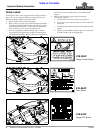
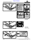
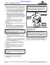
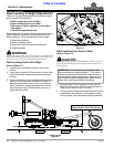
5. Screw jam nuts (#19) onto hitch pins (#20) until 2" of
threads are visible between jam nut and end of pin.
6. Attach hitch pins (#20) and A-frames (#6) as follows:
a. If attaching cutter to a 3-point Cat. I hitch, install
hitch pins (#20) and A-frames (#6) to upper hitch
pins holes “A” with bushings (#4), flat washers
(#17), lock washers (#15), and hex nuts (#11).
b. See Important Note in Figure 1-1 on page 8: If
tractor is too small to lift cutter high enough for
transporting, install hitch pins (#20) and A-frames
(#6) in lower hitch pin holes “B” with bushings (#4),
flat washers (#17), lock washers (#15), and hex
nuts (#11).
c. Tighten hex nuts (#11) to the correct torque.
7. Insert properly sized linchpins (#18) in hitch
pins (#20). (Customer to supply proper sized
linchpins.)
8. Remove hex flange lock nuts (#14) from bolts (#8). Do
not remove bolts.
9. Attach rear braces (#5) inside of tailwheel main
frame (#3) with 5/8"-11 x 1 3/4" GR5 bolts (#8) and
secure with hex flange lock nuts (#14). Draw lock
nuts (#14) up snug and then back off 1/4 turn.
10. Rotate A-frame/floating top hitch (#6 & #13) up and
rotate left rear brace (#5) up as follows:
a. If attaching cutter to a 3-point Cat. I hitch, align
holes A in rear braces (#5) with hole in floating top
hitch (#13).
b. If tractor is too small to lift cutter high enough for
transporting, align hole B in rear braces (#5) with
hole in floating top hitch (#13).
11. Insert 3/4"-10 x 4" GR5 bolt (#9) into the left rear
brace (#5), floating top hitch (#13), and right rear
brace (#5).
12. Secure bolt with hex flange lock nut (#12). Draw
locknut (#12) up snug and then back off 1/4 turn.
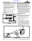
13. Install machine washer (#1A) on tailwheel
spindle (#2).
14. Insert tailwheel spindle (#2) in tailwheel A-frame (#3).
15. Install washer (#1B) on tailwheel spindle (#2).
16. Insert roll pin (#23) on spindle (#2) above
washer (#1B).
IMPORTANT: See Detail A in Figure 1-1 on page 8:
Floating top hitch (#13) must be installed with ears
(#16) above rear brace bars (#5).
NOTE: Bolts (#10) may need to be removed or the
rear of the cutter may need to be raised before tail
wheel spindle (#2) can be inserted into tail wheel A-
frame (#3).
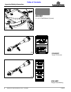
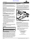
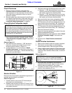
Figure 1-2
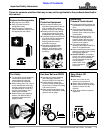
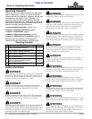
Gearbox Vent Plug
Refer to Figure 1-2:
A vented dipstick for the gearbox is included in a bag with
the manual. See your nearest Land Pride Dealer if
dipstick is missing. Remove temporary red plug from top
of gearbox and replace with supplied vented dipstick.
NOTE: After assembly of hitch and tailwheel, push
on top of A-frame assembly (#6). It should rotate
backward and floating top link (#13) should rotate
upward. If they are too stiff to rotate, loosen nuts
(#12 & #14) until they will rotate freely.
Oil Plug
DO NOT
OVERFILL
Solid
Red Plug
Vented Dipstick
30216
IMPORTANT: Rotary Cutters are shipped with a
solid plug in the gearbox to prevent loss of oil during
shipping and handling. The solid plug on top of the
gearbox must be replaced with a vented dipstick. Do
not operate cutter without vented dipstick installed.