


12
Section 3 Adjustments
FDR15 Rear Discharge Grooming Mowers 310-188M 5/8/08
Land Pride
Table of Contents
Section 3 Adjustments
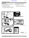
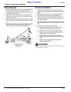
Leveling the Mower
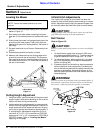
14. Set lower hitches and upper floating hitch, as shown
below in Figure 3-1.
15. Start tractor and raise mower, watching that tractor
draw bar (if not removed) does not interfere with mow-
er.
16. Slowly lower the mower until gauge wheels touch the
ground and the lower mower 3-point hitch bars are
parallel to the ground in floating position. Set tractor 3-
point stop.
17. Set park brake and turn off tractor. Remove key from
ignition.
18. Rotate blades parallel to direction of travel.
19. Measure the clearance from the cutting edge to the
ground at front and rear of the blade. This measure-
ment should be equal or have the blade at the front of
the mower not more than 1/2" lower than the blade at
the rear of the mower.
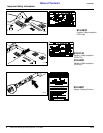
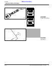
Cutting Height Adjustment
1. Using the tractor, raise the mower off the ground and
support under it with secure blocking so not to let the
mower drift down during maintenance.
2. Holding wheel and yoke assembly up, remove quick-
lock pin from top of gauge wheel spindle. Position full
length spacers and half spacer as required. All spac-
ers on top of spindle tube allows for approximately 3/
4" cutting height. Adjustments range from 3/4" to a
maximum of 3-1/4" in 1/2" increments on FDR1548
mowers and 5 1/4” in 1/2” increments on FDR1560 &
FDR1572 mowers. Refer to “Leveling the Mower”
beginning on this page.
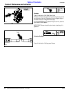
3-Point Hitch Adjustments
The 3-point hitch system on this mower has been de-
signed for front to back flotation when mowing on uneven
terrain. Adjust the tractor’s top link to place the upper hitch
pin vertically above the lower hitch pins as shown below.
!
CAUTION!
Engage parking brake, shut off tractor, remove key and disen-
gage PTO before making any height adjustments!
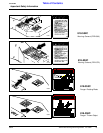
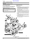
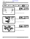
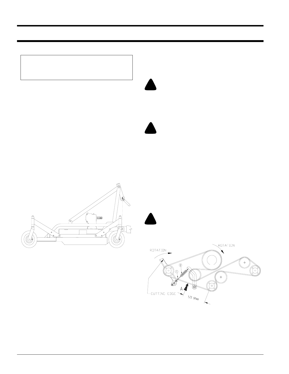
Belt Tension
Refer to Figure 3-2:
!
CAUTION!
Belt drive system under spring tension; use care to avoid bodily
harm!
1. To check tension apply force at arrow A. With a ten-
sion tester and deflect the belt 1/4". The force required
to get this deflection should range from 7 to 10 lbs.
2. To adjust belt tension, adjust eyebolt (#1), as neces-
sary. This adjustment will increase or decrease the
tension on spring (#2).
3. Excessive tension on the belt may lead to premature
failure of belt and drive components. Excessive ten-
sion on the belt may also lead to a safety hazard to the
operator or bystanders. Not enough tension on the
belt may lead to premature failure of the belt due to ex-
cessive slipping.
!
WARNING!
Excessive tension on the belt may lead to premature failure of
belt and drive components. Excessive tension on the belt may
also lead to a safety hazard to the operator or bystanders.
NOTE: Tractor and mower should be on level
ground.
13816
3-Point Hitch
Figure 3-1
Belt Tension
Figure 3-2
13663