


10
Section 1 Assembly and Setup
FDR15 Rear Discharge Grooming Mowers 310-188M 5/8/08
Land Pride
Table of Contents
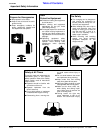
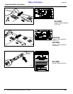
Tractor Hook-Up
1. Be certain that tractor draw bar will not interfere. Move
draw bar ahead or remove if required. Draw bar
should also be checked for clearance when unit is be-
ing raised for the first time.
2. Align lower link arms of tractor to hitch clevises on
mower. Insert lower hitch pins into lower ball swivels
and attach lynch pins.
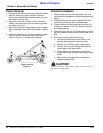
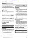
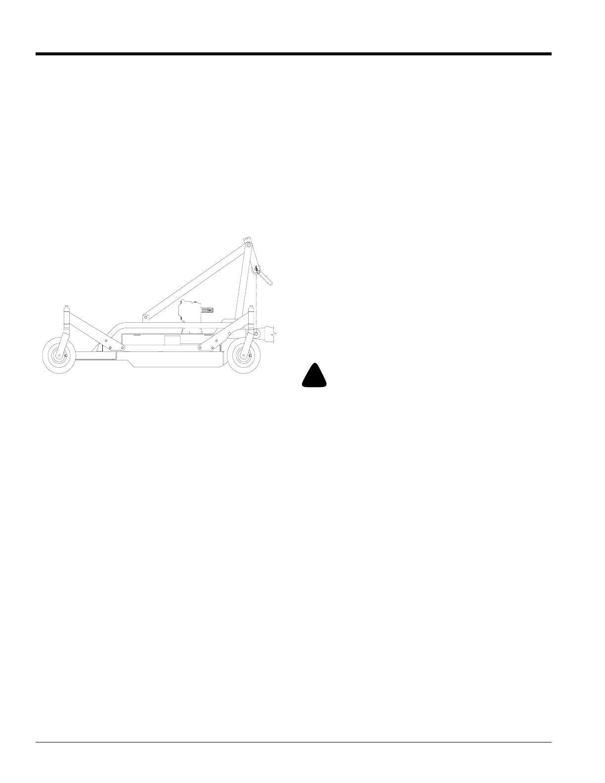
3. Attach tractor top link to upper floating hitch on mower
with pin supplied. Secure with lock pin Refer to Figure
1-2.
4. Adjust the tractor top link in or out to place the upper
hitch pin vertically above the lower hitch pins as
shown in Figure 1-2, to allow mower flotation.
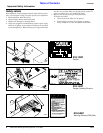
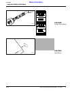
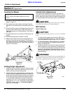
Driveline Installation
1. Slide driveline end with extended safety cone over
splined shaft of the gearbox and secure with attaching
device.
2. Slide driveline over the tractor’s splined PTO shaft
and secure with locking device of powershaft.
3. Driveline should now be moved back and forth to in-
sure that it is secure on the PTO shaft of the tractor
and mower gearbox.
4. Attach the chain from the PTO shield to one of the up-
per hitch braces to ensure that the shield does not ro-
tate.
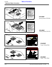
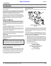
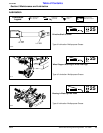
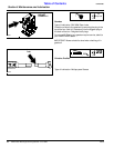
5. Should the driveline require shortening:
a. Hold the half-shafts next to each other in the
shortest working position and mark them.
b. Shorten inner and outer guard tubes equally.
c. Shorten inner and outer sliding profiles by the
same length as the guard tubes.
d. Proper overlap is a minimum of one-half the
length of each tube, with both tubes being of equal
length.
e. Round off all sharp edges and remove burrs.
Grease sliding profiles.
!
CAUTION!
Tractor PTO shield and all mower guards must be in place at
all times during operation!
Tractor Hook-Up
Figure 1-2
13816