


8
Section 1 Assembly and Setup
FD1548 & FD1560 3-Spindle Grooming Mower 310-155M
7/18/08
Land Pride
Table of Contents
Section 1 Assembly and Setup
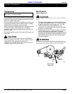
Tractor Requirements
This mower is designed with a 3-Point category I hitch.
Horse power rating of tractor should not exceed 26 PTO
horse power.
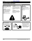
!
CAUTION
Do not over speed PTO or machine damage may result.
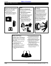
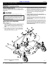
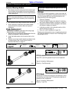
Upper Hitch Arms Assembly
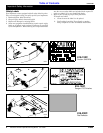
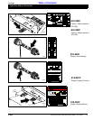
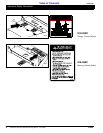
Refer to Figure 1-1:
1. Remove the upper hitch bars (#1), upper hitch braces
(#2), and upper pivoting hitch subassembly (#3)
through (#7) from storage position on top of mower
deck.
2. Bolt the upper hitch braces to the mounting tabs on
back of the deck using 1/2" x 1 1/2" long bolts (#8),
lock washer (#9), and hex nut (#10).
NOTE: In order to maintain steering control, ballast
may have to be added to your tractor front end. To
determine whether or not to add ballast, refer to your
tractor operator’s manual.
3. Mount the upper hitch bars (#1), to the front hitch
plates on the mower frame using the 5/8" x 1 3/4" long
bolts (#11), lock washers (#12) and hex nuts (#13).
4. Remove the 5/8" x 5" long bolt (#5), lock washer (#6),
and hex nut (#7) from the upper pivoting hitch
subassembly.
5. Swing the upper hitch bars (#1) up to a vertical
position. Raise the upper hitch braces (#2) up inside
the upper hitch bars as shown.
6. Assemble the upper pivoting hitch (#3), spacer top
hitch (#4), 5/8" x 5" long bolt (#5), lock washer (#6),
and hex nut (#7).
7. Place the chute (#14) over the square holes on the
right hand side of the deck. Insert the 5/16" carriage
bolts (#15) from the underneath side of the deck.
Secure with the 5/16" nuts (#16) lock washers (#17)
and flat washers (#18).
15033
4-Wheel Unit Upper Hitch Arms Assembly
Figure 1-1