


11
Section 1 Assembly and Set-Up
5/5/08
DM36 Series Disc Mowers 327-045M
Land Pride
Table of Contents
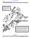
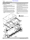
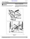
Cutting Unit Assembly
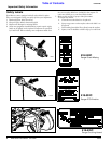
Refer to Figure 1-5:
1. Install the support frame (#2) to the gearbox using the
M16 bolts (#18) and lock washers (#29).
2. Assemble the blade bar support (#4) to the support
frame (#2) using the 3/8” X 2 3/4” long bolts (#15) and
lock nuts (#20).
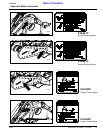
3. Assemble the blade bar support (#4) to the cutting unit
and secure with 1/2” X 1 1/2” bolt (#12), lock washer
(#26) and nut (#21).
4. Attach shield brackets (#7), (#8) and (#9). Bracket
(#7) is assembled with the longer socket head bolt.
Bracket (#8) is assembled with a 1/2” X 1 1/4” long bolt
(#16) and lock nut (#23). Bracket (#9) is assembled
with the shorter socket head bolt (#17) and lock
washer.
5. Assemble shield (#6) to brackets with carriage bolts
(#14), washers (#24) and lock nut (#22).
6. Assemble the guide (#5) to the cutting unit with the
1/2” X 3 1/2” long bolt (#11), flat washer (#27) and lock
nut (#23). Place the spring (#33) between the guide
(#5) and flat washer (#27).
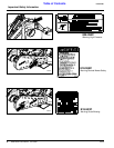
7. Assemble the front tarp frame (#1) and rear tarp frame
(#3) to the support frame (#2) using 3/8” X 2 1/2” bolts
(#13), lock washers, nuts (#20), pins (#32) and hair
pin cotters (#31) to secure.
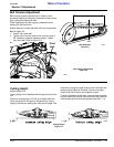
8. Position tarp over frame (#3) so the sewn end is
towards the gearbox with cut out sliding down over
(#2). Pull the other end of the tarp over the other end
of the frame and slip the eyelets over the tarp frame
ends. Fasten tarp to frame using cable ties (#34) and
(#25).
9. Assemble bumpers (#10) to tarp frames with cotter
pins (#30).
Cutting Unit
Figure 1-5
20769
!
DANGER
Do not operate cutting unit without tarp in place!