


8
Section 1 Assembly and Set-Up
DM36 Series Disc Mowers 327-045M 5/5/08
Land Pride
Table of Contents
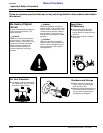
Tools Required
•
Fork lift, crane hoist or block-and-tackle
• Impact wrench or socket and ratchet set (metric)
• Rubber mallet
• Box-end (metric), allen (metric) and crescent wrenches
• Drift pins
• Screwdriver
• Safety shoes, safety glasses and gloves. A hard hat
should be worn by anyone working under the crane.
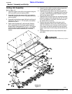
Assembly Preparation
Having all the parts and equipment readily at hand will
speed up your assembly task and make the job as safe as
possible.
Prepare the area where the unit is to be assembled
making sure the area is swept clean of all dust and
contaminants. Un-package the crate and remove all
contents carefully so that the seals on hydraulic
components are not broken or pulled off.
Raise the mainframe with a forklift, hoist or
block-and-tackle and place on pallets or blocks so it is
elevated about 10” off the floor.
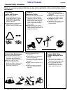
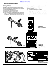
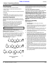
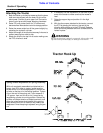
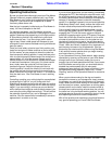
Your cutter bar will already be assembled. It is necessary
to check the direction of rotation of each cutter plate.
Figure 1-1 shows the proper cutter bar plate rotation. If
adjustments need to be made, refer to “Cutter Bar
Timing Adjustment” on page 19.
NOTE: Remove heavy components from crate with a
hoist or block-and-tackle.
Cutter Bar Plate Rotation
Figure 1-1
15144
DM3605
DM3606
DM3607
It is also necessary to check whether the plate turning
right has right cutter blades and the plate turning left has
left cutter blades.
Cutter Bar and Gearbox Lubrication
The cutter bar should arrive with oil already added. After
assembly you may want to check to make sure. For
instructions on how to do this see Lubrication in “Section
4 Maintenance and Lubrication” on page 18 and
“Section 5 Specifications and Capacities” on page 23.
Before operating this unit add SAE 80 GL4 (EP) oil to
gearbox. For further instructions see Lubrication in
“Section 4 Maintenance and Lubrication” on page 18
and “Section 5 Specifications and Capacities” on
page 23.
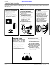
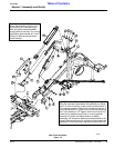
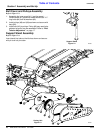
Mainframe Assembly
Refer to Figure 1-2:
1. Insert the gearbox on the cutter unit into the
mainframe lug.
2. Assemble the gearbox pivot (#5) to the mainframe and
gearbox as shown and secure with 3/4” bolts (#13)
and lockwashers (#22).
3. Insert bushing (#2) into transport road latch (#1) and
install on pin located on the cutting unit as shown.
4. Install spring mount (#10) as shown and secure with
3/4” bolt (#14) and lock nut.
5. Assemble spring cushion assembly (#4) to the
mainframe as shown. Assemble the other end of the
spring cushion assembly and hydraulic cylinder (#25)
base end as shown using the long spacer (#9) and
short spacer (#8). Secure with 1” bolt (#12) and lock
nut (#18). Use one of the pins that comes with the
cylinder to attach the lower end in slotted brackets.
6. Assemble spring assembly (#6) to the spring mount
(#10) using 5/8” bolt (#15), flatwashers (#19) and lock
nut (#17) to secure. Assemble the other end of spring
assembly to the cutting unit with long bushing (#9) and
cotter pin (#24).
7. Assemble cylinder extension arm (#7) to the hydraulic
cylinder rod end. Assemble the other end to the same
pin as the road latch (#1) and secure with cotter pin
(#24).
8. Assemble breakaway assembly (#3) to the hitch with
5/8” nut (#16), lock washer (#21) and flat washer (#20)
(spring facing inward).
Section 1 Assembly and Set-Up