


9
Section 1 Assembly and Set-Up
5/5/08
DM36 Series Disc Mowers 327-045M
Land Pride
Table of Contents
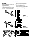
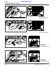
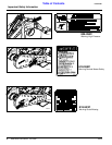
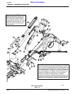
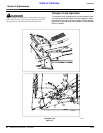
Main Frame Assembly
Figure 1-2
20768
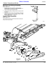
Stroke Control for 3 Pt Disconnect:
When disconnecting unit from 3 Pt,
lock channel (#11) and spring pin
(#23) should be located between
spring tube and rod stop. For running
applications lock channel (#11) and
spring pin (#23) should be stored
below rod stop.
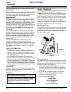
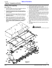
Spring Tension Adjustment for Spring Assembly (#6):
With unit completely assembled and attached to a tractor,
level 3 Pt arms on tractor, (make sure the stroke control is
in the storage position). Retract the cylinder so that bar is
in the vertical position. Tighten nut on the end of the spring
rod (7 disc measure 3 1/2” approx. from end of rod to nut).
Lower bar by lengthening cylinder to running position.
Retract the cylinder and adjust tension as stated
previously until cutter bar raises some what parallel to the
ground. After several hours of run time this may need to be
readjusted. Once the spring is adjusted, snug the jam nut.