28
Section 5: Maintenance and Lubrication
AFM4011, AFM4014 and AFM4016 All Flex Grooming Mowers 315-160M
7/28/06
Land Pride
Table of Contents
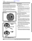
Clutch Assembly
Clutches With 8-Alan Head Socket Bolts
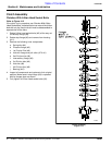
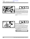
Refer to Figure 4-12
If the clutch run-in procedure, see Clutches With 8-Alan
Head Socket Bolts, indicated that one or more of the friction
disks did not slip, then the clutch must be disassembled to
separate the friction disks.
1. Rotate 8 Alan head socket bolts (#2) all the way out
to free stop flange (#3).
2. Rotate stop flange (#3) and remove from housing
(#11).
3. Remove the following inner components:
a. Spring disc (#4)
b. Pressure flange (#5)
c. 1st Friction Disc (#6)
d. Hub with flange and pull collar (#7 & #1)
e. 2nd Friction disc (#6)
f. Intermediary flange (#8)
g. 3rd Friction disc (#6)
h. Hub disc (#9)
i. 4th Friction disc (#6)
j. Bearing (#10)
4. Inspect all components and replace to their original
position. Make certain stop flange (#3) is replaced
with its flanges down as shown.
5. Fully tighten all 8 Alan head socket bolts (#2).
Clutch Assembly
Figure 4-12
21303


