


TP-6331 5/0420 Section 4 Troubleshooting
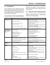
4.3 Fault Codes
The Advanced Digital Control displays fault codes to aid
in troubleshooting. Fault codes, descriptions, and
recommended actions are listed in Figure 2-3.
Identify and correct the cause of the fault condition.
Then reset the controller after a fault shutdown. See
Section 2.4.1.
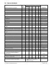
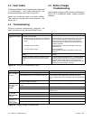
4.4 Troubleshooting
Figure 4-2 contains troubleshooting, diagnostic, and
repair information for the Advanced Digital Control.
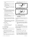
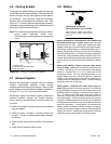
4.5 Battery Charger
Troubleshooting
Use the battery charger’s LED indicators and the table in
Figure 4-3 to troubleshoot battery charger operation
problems.
Problem Possible Cause Corrective Action
Controller LED display
is off
No power to the controller:
Continuous power mode jumper is disconnected
and the generator set has not run for 48 hours or
longer.
Controller display will automatically activate when a remote
start command is received or the generator set master
switch is moved to the RUN position. See Section 2.5.
Connect the jumper to maintain continuous power to the
controller, if desired.
Controller fuse (F3) is blown. Replace the fuse. If the fuse blows again, contact the
distributor/dealer.
Low or no battery voltage. Check connections.
Check generator set battery and battery charger. See
Figure 4-1.
Generator set master switch is in the OFF/RESET
position.
Move generator set master switch to the AUTO or RUN
position.
Generator set master switch in AUTO but no start
command has been received since last controller
reset.
No action required (see Section 2.3.1). Controller display
will activate when a remote start command is received or
the generator set master switch is moved to the RUN
position. Use the remote switch to start generator set and
activate the controller display, if desired.
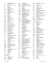
Figure 4-2 ADC 2100 Troubleshooting Chart
Problem Cause Solution
Red LED stays
f
t
h
One or more defective or damaged cells. Load test the battery and replace, if necessary
y
on for more than
24 hours
Battery charger has reduced its output voltage below
the normal level due to a DC overload or a DC short.
Remove the source of the overload or short. Disconnect the
battery charger’s black (NEGATIVE) ring terminal from the
battery. Reapply AC power and the green LED only should now
light.
Onboard DC systems are drawing more current than
the battery charger can replace.
Turn off all DC equipment while charging.
Red and green
LEDs stay on for
t
h
Onboard DC systems are drawing between 1.5 and
5amps.
Turn off all DC equipment while charging.
y
more than
2
4
h
o
u
r
s
One or more defective or damaged cells. Load test the battery and replace, if necessary
2
4
h
ours
Extremely low AC voltage at the battery charger. Apply a higher AC voltage source or reduce the length of the
extension cord.
Green LED stays
h
t
h
Open DC output fuse. Replace AGS-10 fuse.
y
on when the
b
a
tter
y
is known
Faulty or contaminated terminal connections. Clean and tighten or repair all terminal connections.
b
a
t
t
e
r
y
i
s
k
n
o
w
n
to be low
One or more defective or damaged cells. Load test the battery and replace, if necessary.
Neither of the
LEDs turn on
No AC power available at the battery charger. Connect AC power or reset the AC breaker on the main panel.
L
E
D
s
t
u
r
n
o
n
when the AC
power is applied
Component failure. Replace battery charger.
Figure 4-3 Battery Charger Troubleshooting