


TP-6331 5/04 3Section 2 Operation
Section 2 Operation
2.1 Prestart C hecklist
To ensure continued satisfactory operation, perform the
following checks or inspections before or at each
startup, as designated, and at the intervals specified in
the service schedule. In addition, some checks require
verification after the unit starts.
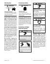
Air Cleaner. Check for a clean and installed air cleaner
element to prevent unfiltered air from entering the
engine.
Air Inlets. Check for clean and unobstructed air inlets.
Battery. Check for tight battery connections. Consult
the battery manufacturer’s instructions regarding
battery care and maintenance.
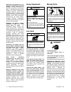
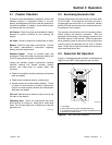
Exhaust System. Check for exhaust leaks and
blockages. Check the muffler and piping condition and
check for tight exhaust system connections.
Inspect the exhaust system components (exhaust
manifold, exhaust line, flexible exhaust, clamps,
silencer, and outlet pipe) for cracks, leaks, and
corrosion.
D Check for corroded or broken metal parts and replace
them as needed.
D Check that the exhaust outlet is unobstructed.
D Visually inspect for exhaust leaks (blowby). Check
for carbon or soot residue on exhaust components.
Carbon and soot residue indicates an exhaust leak.
Seal leaks as needed.
Oil Level. Maintain the oil level at or near, not over, the
full mark on the dipstick.
Operating Area. Check for obstructions that could
block the flow of cooling air. Keep the air intake area
clean. Do not leave rags, tools, or debris on or near the
generator set.
x:op:001:002
2.2 Exercising Generator Set
Operate the generator set without load once each week
for 20 minutes. If the generator set does not have a
programmed exercise mode or an automatic transfer
switch (ATS) with an exercise option, exercise the unit in
the presence of an operator.
The operator should perform all of the prestart checks
before starting the exercise procedure. Start the
generator set according to the starting procedure in the
controller section of this manual. While the generator
set is operating, listen for a smooth-running engine and
visually inspect the generator set for fluid or exhaust
leaks. Check the air inlets and outlets and remove any
items restricting the air flow.
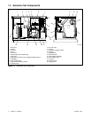
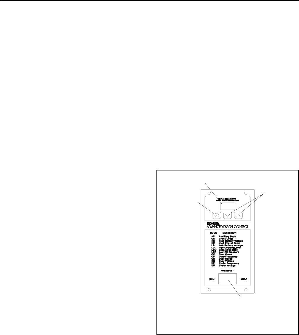
2.3 Generator Set Operation
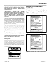
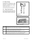
Figure 2-1 illustrates the user interface on the Advanced
Digital Control (ADC 2100) generator set controller.
GM28707A-C
1. LED display
2. Select button (use for setup and adjustment only)
3. Up anddown arrowbuttons (usefor setup andadjustment only)
4. Generator set master switch
1
2
4
3
Figure 2-1 ADC 2100 User Interface