


TP-6331 5/044 Section 2 Operation
2.3.1 Controls and Indicators
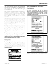
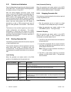
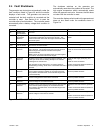
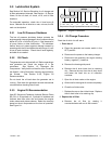
Figure 2-2 describes the controls and indicators located
on the ADC 2100. The LED display indicates generator
set status as shown in Figure 2-2.
With the factory-installed continuous power mode
jumper in place, the LED display is activated when the
generator set master switch is moved to the RUN or
AUTO position and remains active until the master
switch is moved to the OFF/RESET position or power to
the controller is removed. If the continuous power mode
jumper has been disconnected, the LED display is
activated by a start or RUN command and turns off
48 hours after generator set shutdown. See Section
2.5.
The buttons on the controller keypad are used only for
system configuration and adjustment. The system
configuration is factory-set and should not require
changes under normal operating conditions. Contact an
authorized distributor/dealer or service technician if
adjustments are required.
2.3.2 Starting Generator Set
The following procedures describe the actions required
to start the generator set.
The controller attempts to start the generator set three
times (three crank cycles, 15 seconds crank and
15 seconds off). If the generator set does not start in
three attempts, the system shuts down on an overcrank
fault.
Local Starting
Move the generator set master switch to the RUN
position to immediately start the generator set.
Auto (Automatic) Starting
Move the generator set master switch to the AUTO
position to allow startup by an automatic transfer switch
(ATS) or remote start/stop switch, if equipped.
2.3.3 Stopping Generator Set
The following procedures describe the actions required
to stop the generator set.
Local Stopping
1. Run the generator set at no load for at least
2 minutes to ensure adequate engine cooldown.
2. Move the generator set master switch to the
OFF/RESET position. The engine stops.
Automatic Stopping
With the generator set master switch in the AUTO
position and an (ATS) or other automatic device
connected to controller leads 3 and 4:
1. The ATS or other device disconnects the load from
the generator set.
2. If the ATS is equipped with an engine cooldown
time delay, the generator set continues to run for a
preset engine cooldown time.
Note: There is no engine cooldown time delay on
the ADC controller.
3. The ATS or other device opens the connection
between controller leads 3 and 4. The generator
set shuts down.
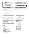
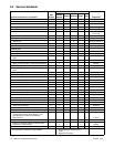
Control or Indicator Item Description
LED display
Runtime hours Displays total generator set runtime hours while the generator set is running and when no
other codes are displayed.
Crank indication Displays CC_1, CC_2, or CC_3 to indicate the first, second, or third attempt to start the
engine. The last digit flashes during the crank cycle rest periods.
Fault codes Flashes a 2- or 3-letter fault code to indicate various fault conditions. See Section 2.4.
Software version
number
See TP-6196, Generator Set Service Manual. Contact an authorized distributor/dealer.
Keypad Select and arrow
buttons
The keypad is used for controller setup and adjustment only. Have setup and adjustments
performed only by an authorized distributor/dealer. The setup and adjustment functions are
password-protected.
Generator set master
switch
Three-position
switch
Switch functions as the generator set operation and controller reset switch.
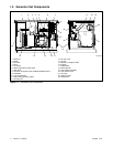
Figure 2-2 ADC 2100 Controls and Indicators