


TP-6069 6/03 69Section 8 Reconnection/Adjustments
Note: Position the current transformers with the
dot or HI side CT marking toward the
generator set.
Note: Only generator sets equipped with ACmeter
controllers and/or safeguard circuit
breakers require CTs.
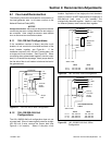
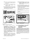
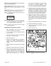
5. If the controller has meters, remove the controller
cover and reposition the meter scale lamp jumper
(see Figure 8-6) matching the position of the
desired voltage (shown in Figure 8-5).
TP-5353-6
1
1. Lamp Jumper
Figure 8-6 Meter Scale Lamp Jumper
6. The overvoltage shutdown is standard on
Decision-Makert 3+ controllers. The
139/240-volt (low wye) and 277/480-volt (high
wye), 3-phase, 4-wire, 60 Hz configurations use
different overvoltage shutdown settings than all
other configurations. Recalibrate the overvoltage
shutdown if the reconnection changes the voltage
to or from one of these configurations. See
Section 8.3, Decision-Maker 3+ Controller,
Overvoltage Shutdown Adjustment. Do not
recalibrate the overvoltage adjustment for other
voltage changes.
7. If the controller has meters, set the phase selector
switch to the L1-L2 position (1-phase or 3-phase
configuration depending on generator set
connection). Connect a voltmeter across leads L1
and L2 if the controller has no meters.
Note: Equipmentdamage. Verify that the voltage
ratings of the transfer switch, line circuit
breakers, and other accessories match the
desired line voltage.
8. Reconnect the starting battery, negative (--) lead
last. Place the generator set master switch in the
RUN position to start the generator set. Observe
the voltmeter and verify that the unit has the
desired line voltage connection.
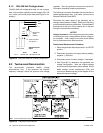
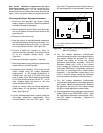
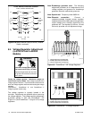
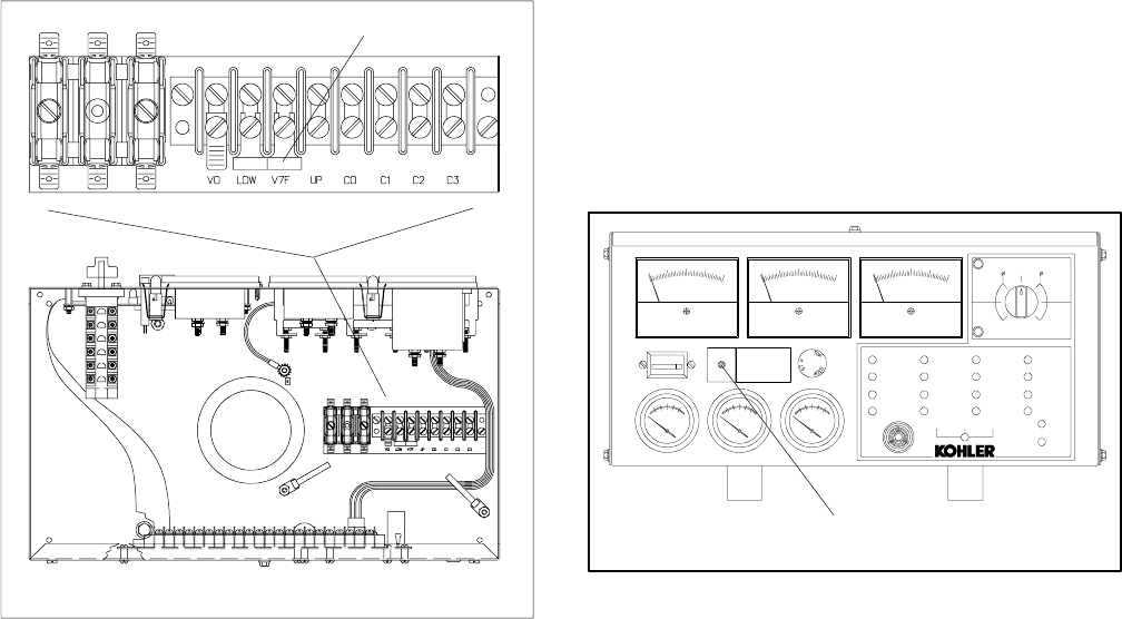
Adjust the voltage using the voltage adjustment
potentiometer on the generator controller front
panel. See Figure 8-7.
9. Stop the generator set after completing the voltage
adjustment.
10. Disconnect the externalvoltmeter ifused. Replace
the controller cover.
ADV-5849A-
1
1. Output voltage adjustment potentiometer
EMERGENCY
STOP
ONLY
OFF/RESET
PREALARM
HIGHENGINE
TEMPERATURE
PREALARM
LOWOIL
PRESSURE
LOWWATER
TEMPERATURE
LOWFUEL
HIGHENGINE
TEMPERATURE
LOWOIL
PRESSURE
EMERGENCY
STOP
OVERSPEED
AUXILIARY
FAULT
BATTERY
CHARGERFAULT
LOWBATTERY
VOLTAGE
OVERCRANK
AUXILIARY
PREALARM
AIR
DAMPER
SYSTEM
READY
GENERATOR
SWITCH
NOTINAUTO
NORMALSILENCE
LAMP TEST
ALARM
AUTORUN
HERTZ A--CVOLTS A--CAMPERES
BATTERY
WATER
TEMP
OIL
PRESS
00000
TOTALHOURS
LOWERMETERSCALES
3
OFF
1
UPPERMETERSCALES
AMPS
VOLTS
L0--L1
L3
L3--L1
L2
L1--L2
L1
L1--L2
L1
L1--L2
L2
L2--L3
S
VOLTAGE
ADJUST
O
Figure 8-7 Voltage Adjustment
Thisis bpid
8.3 Decision-Maker 3+ Controller,
Overvoltage Shutdown
Adjustment
Disconnectingtheelectricalload. Hazardous voltagecan
cause severe injury or death. Disconnect the generatorset
from the load by opening the line circuit breaker or by
disconnectingthegenerator setoutput leads from thetransfer
switch and heavily taping the ends ofthe leads. High voltage
transferred to the load during testing may cause personal
injury and equipment damage. Do not use the safeguard
circuit breaker in place of the line circuit breaker. The
safeguard circuit breaker does not disconnect the generator
set from the load.