


TP-6069 6/03 21Section 6 Electrical System
Disabling the generator set. Accidental starting can
cause severe injury or death. Before working on the
generator set or equipment connected to the set, disable the
generatorsetasfollows: (1) Placethegeneratorsetstart/stop
switch in the STOP position. (2) Disconnect the power to the
battery charger, if equipped. (3) Remove the battery cables,
negative (--) lead first. Reconnect the negative (--) lead last
when reconnecting the battery. Follow these precautions to
prevent the starting of the generator set by the remote
start/stop switch.
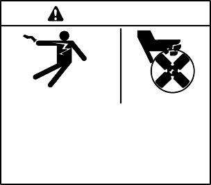
Hazardous voltage.
Can cause severe injury or death.
Operate the generator set only when
all guards and electrical enclosures
areinplace.
Movingrotor.
WARNING
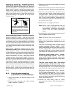
Grounding electrical equipment. Hazardous voltage can
cause severe injury or death. Electrocution is possible
whenever electricity is present. Open the main circuit
breakersofall powersources before servicing theequipment.
Configure the installation to electrically ground the generator
set, transfer switch, and related equipment and electrical
circuitstocomplywithapplicablecodesandstandards. Never
contact electrical leads or appliances when standing in water
oronwetgroundbecausetheseconditionsincreasetheriskof
electrocution.
Short circuits. Hazardous voltage/current can cause
severeinjury or death. Shortcircuits can cause bodily injury
and/or equipment damage. Do not contact electrical
connectionswith tools or jewelry while making adjustments or
repairs. Remove all jewelry before servicing the equipment.
Electrical backfeed to the utility. Hazardous backfeed
voltage can cause severe injury or death. Connect the
generator set to the building/marina electrical system only
through an approved device and after the building/marina
main switch is opened. Backfeed connections can cause
severe injury or death to utility personnel working on power
lines and/or personnel near the work area. Some states and
localities prohibit unauthorized connection to the utility
electrical system. Install a ship-to-shore transfer switch to
prevent interconnection of thegenerator setpower andshore
power.
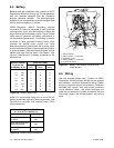
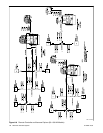
6.2.2 Circuit Breaker Installation
(4--27EFOZ and 5--32EOZ Models)
1. Place the generator set start/stop switch in the
STOP position.
2. Disconnect the generator set engine starting
battery, negative (--) lead first.
3. Remove the controller cover screws and remove
the access cover.
4. Remove the screws and nuts to remove the circuit
breaker cover plate. Save the mounting hardware.
5. Install the circuit breaker from the inside of the
cutout panel and mount it using existing screws
removed in step 4. Position the circuit breaker with
the ON in the normal upright position or to the left
side. Cover the cutout opening, if applicable, with
thecircuit breaker cover plate. Useexisting screws
to mount the cover plate.
6. See Section 8 for voltage reconnection.
Note: Kohlerr marine diesel generator sets are
fully frequency adjustable and voltage
reconnectable. To determine reconnection
options, check the model’s specification
sheet.
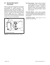
7. Install insulation boots over stator lead terminals if
the kit includes insulation boots.
Note: See Section 8 for wiring instructions.
8. Make the recommended connections for the
following four reconnection systems using circuit
breakers:
Two-pole circuit breaker with a single-voltage
system (example: 120-volt, 3-wire). Attach
stator leads marked2 and4 to the sideof thecircuit
breaker marked LINE. Install the jumper lead
across the LINE side of circuit breaker terminals
(see Section 8). Attach stator leads 1 and 3 to L0.
Single-pole circuit breaker with a 120-volt,
2-wire, single-voltage system. Attach stator
leads marked 2 and 4 to the side of the circuit
breakermarked LINE (see Section 8). Attachstator
leads 1 and 3 to L0.
Two-pole circuit breaker with a dual-voltage
system (example: 120/240-volt, 3-wire). Attach
stator leads marked1 and4 to the sideof thecircuit
breaker marked LINE. Do not use a jumper lead
(see Section 8). Attach stator leads 2 and 3 to L0.
Single-pole circuit breaker with a 240-volt,
2-wire, single-voltage system. Attach the stator
lead marked 2 to the side of the circuit breaker
marked LINE (see Section 8). Bolt together leads 1
and 4 and tape to insulate from ground. Attach the
stator lead marked 3 to L0.
9. Connect the stator lead(s) used for neutral
connection to the L0 stud. See the illustrations in
Section 8.