


TP-6069 6/03 19Section 6 Electrical System
Section 6 Electrical System
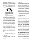
Hazardous voltage.
Can cause severe injury or death.
Operate the generator set only when
all guards and electrical enclosures
areinplace.
Movingrotor.
WARNING
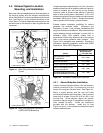
Electrical backfeed to the utility. Hazardous backfeed
voltage can cause severe injury or death. Connect the
generator set to the building/marina electrical system only
through an approved device and after the building/marina
main switch is opened. Backfeed connections can cause
severe injury or death to utility personnel working on power
lines and/or personnel near the work area. Some states and
localities prohibit unauthorized connection to the utility
electrical system. Install a ship-to-shore transfer switch to
prevent interconnection of thegenerator setpower andshore
power.
1
2
3
4
5
6
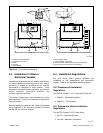
585771
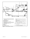
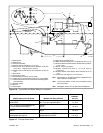
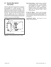
1. Line side
2. AC circuit breaker
3. Load side
4. L1/L2 phase (black) leads
5. GRD ground (green) lead
6. L0 neutral (white) lead
Figure 6-1 AC Voltage Connections in Controller
Box (5--32EOZ Models, Typical)
6.1 AC Voltage Connections
Make AC connections to the generator set inside the
controller box (4--27EFOZ and 5--32EOZ models) or
inside the junction box (33--125EFOZ and 40--150EOZ
models). Typically, the generator set connects to a
ship-to-shore transfer switch that allows the use of
shore/utility power when docked or generator set power
when docked or at sea. The wiring then connects to a
main circuit breaker box (panel board) that distributes
branch circuits throughout the craft. See Figure 6-1 for
AC voltage connections to the generator set. See
Section 8 for reconnection of the generator set.
6.2 Circuit Protection
The AC circuit breakers (optional) protect the wiring
from the AC circuit breakers to the vessel’s distribution
panel. AC circuit breakers trip when they detecta fault in
the output circuit.
After correcting the fault, reset the AC circuit breaker(s)
by placing them in the ON position. Restart the unit. Do
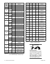
not start the unit under load. See Figure 6-2 or
Figure 6-3 for AC circuit breaker ratings. The unit’s
voltage configuration determines the circuit breaker
selection.
Note: Circuit breaker ampere rating and availability are
subject to change.
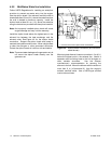
6.2.1 Circuit Breaker Considerations
Mounting location. Mount the circuit breakers in the
generator set’s controller (4--27EFOZ and 5--32EOZ
models) or the generator set’s junction box
(33--125EFOZ and 40--150EOZ models). See
Section 6.2.2 or Section 6.2.3.
Note: 3.5EFOZ and 4EOZ models already have circuit
breakers installed.
Sizing. Use the generator set voltage/frequency
configuration to determine the circuit breaker
amperage. If the generator set voltage configuration
changes, change the circuit breaker to provide optimum
protection.
For circuit breaker application and selection
information, contact an authorized distributor/dealer.
Have a qualified electrician or technician install circuit
breakers and reconnect the generator set. Comply with
all governing standards and codes.