


TP-6804 1/15 31Section 3 RDC2 Controller Operation
Section 3 RDC2 Controller Operation
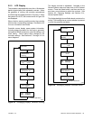
3.1 RDC2 Generator Set/Transfer
Switch Controller
Model RESA generator sets are equipped with the
RDC2 generator set/transfer s witch controller. See
Figure 3-1 for controller illustrations. The operation is
the same for the original and revised controllers.
Model RESAL generator sets are equipped with the
DC2 controller. See Section 4 for DC2 controller
operation information.
The RDC2 controls the following power system
components:
D Model 14RESA or 20RESA generator set
D Model RXT Automatic Transfer Switch (ATS)
D Load Control Module (LCM) or load shed kit
D Programmable Interface Module (PIM)
The RDC2 controller features include:
D Two-line x 16 character backlit digital display with
adjustable contrast
D OFF, AUTO, and RUN generator set master c ontrol
buttons
D Generator set status indicating LEDs (OFF, AUTO,
RUN)
D Up, Down, and Select buttons for navigation through
menus and adjustments
D Power system indicator LEDs to show utility and
generator source status, and to show which source
(utility or generator) is supplying power to the load
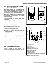
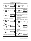
3.2 Controls and Indicators
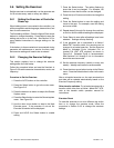
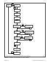
Figure 3-1 illustrates the RDC2 controller. See
Figure 3-2 for details of the controller’s user interface.
1. User Interface; see Figure 3-2
1
GM77569
GM90304
Original RDC2 Revised RDC2
Figure 3-1 RDC2 Controls and Indicators
9
1. 2-line LCD display
2. Up button
3. Select button
4. Down button
5. RUN button and LED
6. Generator power available LED*
7. Building on generator power LED*
8. Building on utility power LED*
9. Utility power available LED*
10. OFF button and LED
11. AUTO button and LED
* These LEDs operate only if a Model RXT transfer switch is
connected.
1
10
3
2
5
11
4
GM77569
687
Figure 3-2 RDC2 User Interface