TP-6804 12/1116 Section 1 Descriptions and Service Views
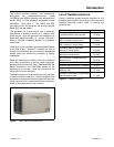
The controller’s 2-line LCD screen displays status
messages and system settings that are clear and easy
to read, even in direct sunlight or low light.
RDC2 Controller Features
D Six-button keypad
d OFF, AUTO, and RUN pushbuttons
d Select and arrow buttons for access to system
configuration and adjustment menus
D LED indicators for OFF, AUTO, and RUN modes
D LED indicators for utility power and generator set
source availability and ATS position (Model RXT
transfer switch required)
D LCD display
d Two lines x 16 characters per line
d Backlit display with adjustable contrast for
excellent visibility in all lighting conditions
D Scrolling system status display
d Generator set status
d Voltage and frequency
d Engine temperature
d Oil pressure
d Battery voltage
d Engine runtime hours
D Date and time displays
D Smart engine cooldown senses engine temperature
D Digital isochronous governor to maintain
steady-state speed at all loads
D Digital voltage regulation: ±0.5% RMS no-load to
full-load
D Automatic start with programmed c ranking cycle
D Programmable exerciser can be set to start
automatically on any future day and time, and run
every week or every two weeks
D Exercise modes
d Unloaded weekly exercise with complete system
diagnostics
d Unloaded full-speed exercise
d Loaded full-speed exercise (Model RXT ATS
required)
D Front-access mini USB connector for SiteTecht
connection
D Front access mini-breaker protects the alternator
D Integral Ethernet connector for Kohlerr OnCuet
D Built-in 2.5 amp battery charger
D Remote two-wire start/stop capability for optional
connection of Model RDT or RSB transfer switches
D Diagnostic messages
d Displays diagnostic messages for the engine,
generator, Model RXT transfer switch,
programmable interface module (PIM), and load
control module (LCM)
d Over 70 diagnostic messages can be displayed
D Maintenance reminders
D System settings
d System voltage, frequency, and phase
d Voltage adjustment
d Measurement system, English or metric
D ATS status (Model RXT ATS required)
d Source availability
d ATS position (normal/utility or
emergency/generator)
d Source voltage and frequency
D ATS control (Model RXT ATS required)
d Source voltage and frequency settings
d Engine start time delay
d Transfer time delays
d Voltage calibration
d Fixed pickup and dropout settings
D Programmable Interface Module (PIM) status
displays
d Input status (active/inactive)
d Output status (active/inactive)
D Load control module (LCM) menus
d Load status
d Test function


