


8
Call 1-866-576-8388 for missing parts or assembly help
DO NOT RETURN TO STORE
ASSEMBLY INSTRUCTIONS FOR TRACTORS WITH
DUAL MOWER DECK SUSPENSION BRACKETS
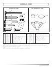
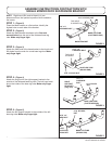
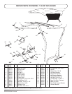
STEP 1: (Figure 8)
Identify and position the right base bracket as shown in
gure 6. Attach the right base bracket to the front holes of
a round base leg tube. Make only nger tight. Repeat
for the left base bracket.
FIGURE 8
5/16" x 2-3/4"
CARRIAGE BOLT
5/16" NYLOCK
NUT
SPACER
RIGHT BASE BRACKET
BASE LEG TUBE
(ROUND END)
LEFT BASE
BRACKET
HIGHEST HOLE
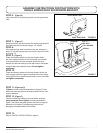
STEP 2: (Figure 9)
Insert the ends of the base leg tubes into the upper base
tube.
FIGURE 9
UPPER BASE TUBE
BASE TUBE LEGS
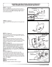
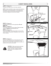
STEP 3: (Figure 10)
Raise the tractor seat and remove the springs and bolts
from the rear fender using a 1/2" socket for GT tractors or
a 9/16" socket for LT tractors.
STEP 4:
Place the base tube assembly onto the rear fender.
Check for clearance with the seat lowered and the rear
bagger (optional) attached. If needed, reposition the base
brackets to a different set of holes in the base tubes.
STEP 5: (Figure 10)
Attach the seat springs and the base brackets to the rear
fender using the spring bolts that you removed. On GT
tractors, if the bolts removed were less than 1" long, use
5/16" x 1" bolts and 5/16" washers from the parts bag.
Align the base leg tubes on the rear fender. Tighten with
moderate force using a 1/2" socket (GT) or a 9/16" socket
(LT).
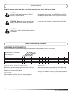
STEP 6: (Figure 11)
If the base tubes rest down against the top of the
fender, install the rear base support brackets. Attach an
adhesive pad to the bottom of each bracket then attach
the brackets to the appropriate holes in the base support
tubes. Adjust the brackets to lift the base tubes above the
fender, then tighten.
STEP 7:
Tighten the bolts assembled in step 1.
STEP 8:
Continue to CANOPY INSTALLATION on page 9.
FIGURE 10
ORIGINAL BOLT
OR BOLT AND
WASHER
SPRING
ADJUST
TO FIT
FIGURE 11
5/16" X 2"
CARRIAGE BOLT
5/16" NYLOCK NUT
REAR SUPPORT BRACKET
ADHESIVE PAD