


6
Call 1-866-576-8388 for missing parts or assembly help
DO NOT RETURN TO STORE
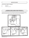
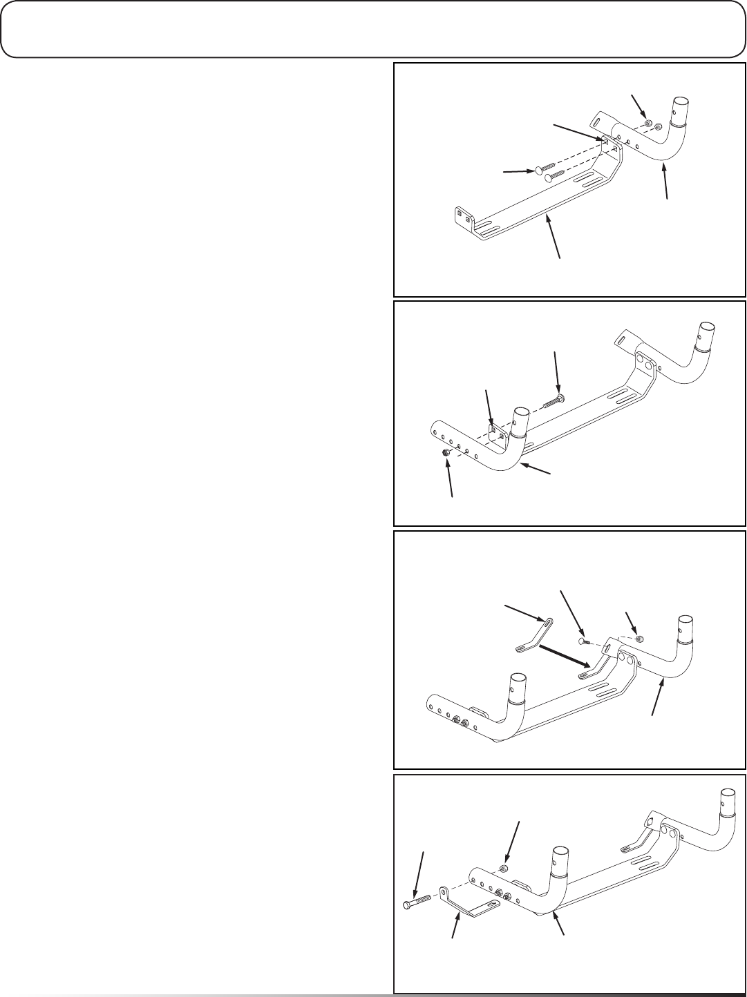
5/16" x 2"
CARRIAGE BOLT
5/16" NYLOCK NUT
BASE BRACKET
BASE LEG TUBE
(FLATTENED END)
THIS HOLE
IS HIGHER
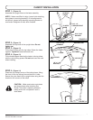
FIGURE 2
NOTE: Right hand (RH) and left hand (LH) are
determined from the operator's position while seated on
the tractor.
STEP 1: (Figure 2)
Place the base bracket on a at surface. Identify the
highest hole on each side of the bracket.
STEP 2: (Figure 2)
Attach the base bracket as shown to the rst and
second holes from the end of the attened base leg
tube. Make only nger tight.
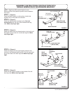
STEP 4: (Figure 4)
Attach the long end of the right support bracket to the
outside of the attened base leg tube. The bolt head must
be on the inside of the base leg tube. Make only nger
tight.
5/16" x 2"
CARRIAGE BOLT
5/16" NYLOCK NUT
BASE LEG TUBE
(ROUND END)
THIS HOLE
IS HIGHER
FIGURE 3
ASSEMBLY INSTRUCTIONS FOR TRACTORS WITH
SINGLE MOWER DECK SUSPENSION BRACKET
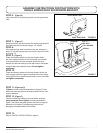
FIGURE 4
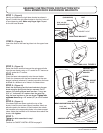
FIGURE 5
1/4" NYLOCK
NUT
1/4" x 1"
CARRIAGE
BOLT
BASE LEG TUBE
(FLATTENED END)
RIGHT
SUPPORT
BRACKET
(long end)
5/16" x 2"
HEX BOLT
5/16" NYLOCK
NUT
LEFT
SUPPORT
BRACKET
BASE LEG TUBE
(ROUND END)
STEP 5: (Figure 5)
Attach the left support bracket to the outside of the left
base leg tube. Make only nger tight.
STEP 3: (Figure 3)
Attach the other end of the base bracket to the fourth and
fth holes from the end of a round base leg tube. Make
only nger tight.