English – 19
ASSEMBLY
Fitting the trimmer guard and
trimmer head Trimmy SII
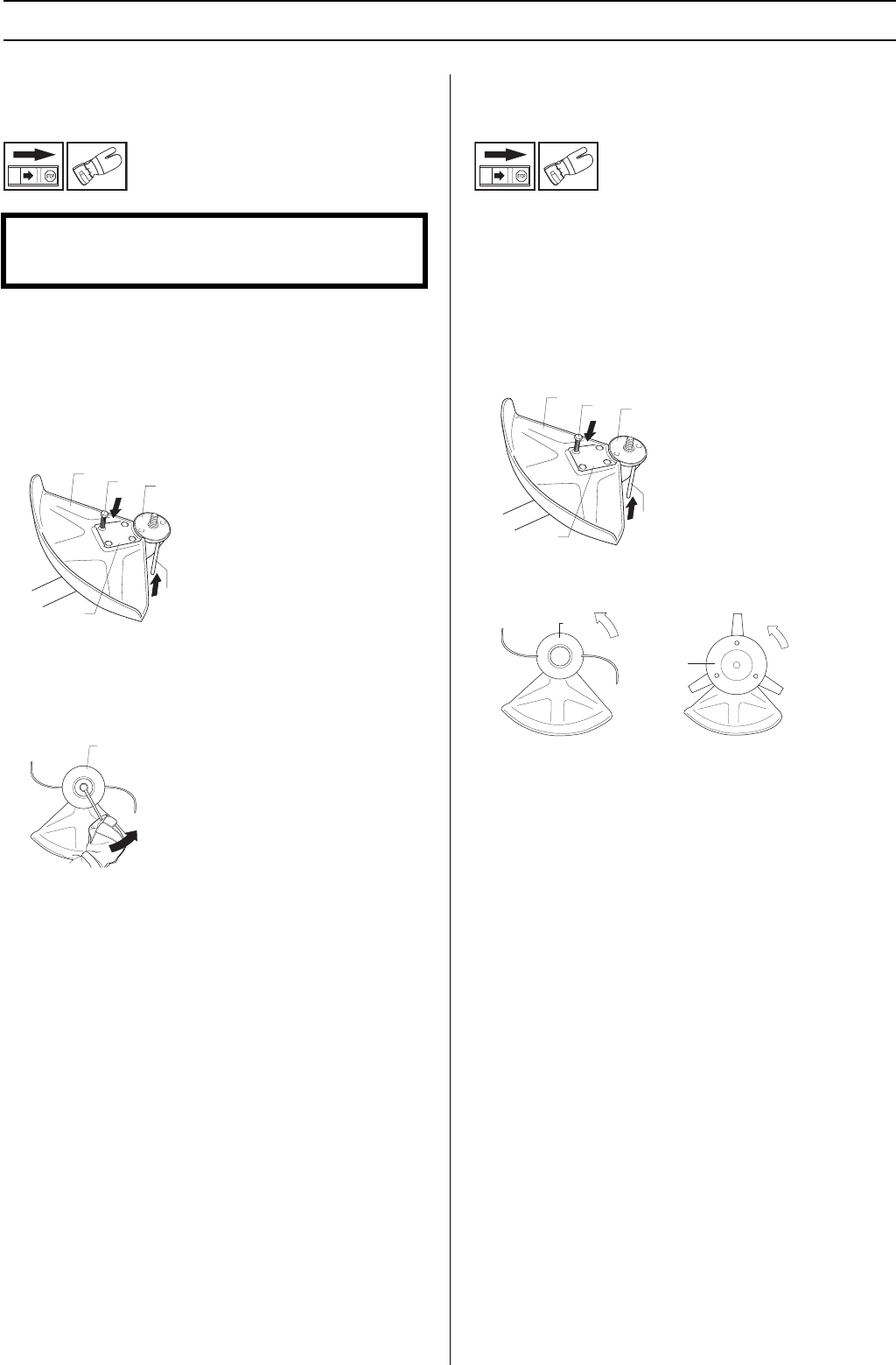
• Fit the correct trimmer guard (A) for use with the trimmer
head. Secure the trimmer guard using the 4 screws (L)
and the support plate (M) as shown.
• Fit the drive disc (B) on the output shaft.
• Turn the blade shaft until one of the holes in the drive disc
aligns with the corresponding hole in the gear housing.
• Insert the locking pin (C) in the hole to lock the shaft.
• Screw on the trimmer head (H) in the opposite direction to
the direction of rotation.
• Tighten the trimmer head to a torque of 35-50 Nm (3.5-5
kpm).
• To dismantle, follow the instructions in the reverse order.
Fitting other guards and cutting
attachments
Fit the trimmer guard/combination guard (A) intended for use
with the trimmer head/plastic blades. Secure the trimmer
guard using the 4 screws (L) and the support plate (M) as
shown.
• Fit the drive disc (B) on the output shaft.
• Turn the blade shaft until one of the holes in the drive disc
aligns with the corresponding hole in the gear housing.
• Insert the locking pin (C) in the hole to lock the shaft.
• Screw on the trimmer head/plastic blades (H) in the
opposite direction to the direction of rotation.
• To dismantle, follow the instructions in the reverse order.
CAUTION! If the machine is to be used with a trimmer
head, the fast idle speed must be reduced by 400-500 rpm.
See instructions under the heading Carburettor.
B
A
L
M
C
H
B
A
L
M
C
H
H


