


English – 43
Assembly
1. If the throttle lock has been removed, this must
be assembled before the tank unit and engine
unit are assembled.
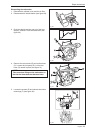
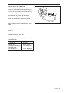
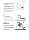
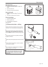
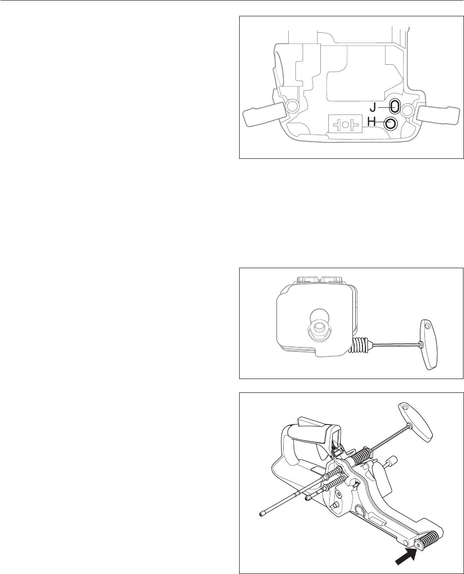
2. Lift the engine unit above the tank unit and
insert the fuel hose (in J), return hose (in H) in
the bottom of the carburettor compartment (see
gure 48).
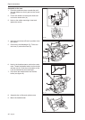
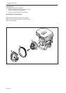
3. Fit the handle with the screws (A). Tighten the
screws with the torque set out in the service
data (see gure 46).
4. Fit the fuel hose (B) and fuel pump return hose
(D) on the carburettor (see gure 45).
5 Mount the throttle actuator rod (see gure 45).
6 Assemble the cylinder cover, bar and chain.
See the Operator's Manual.
Repair instructions
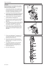
7.18 Vibration damping system
Dismantling
1. Dismantle the following parts:
• Bar and chain. See the Operator's Manual.
• Cylinder cover. See the Operator's Manual.
• Tank unit and handle.
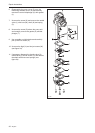
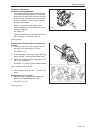
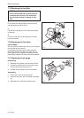
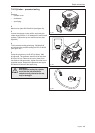
2. Dismantle the spring on the cylinder with the
help of a 5 mm allen key (see gure 49).
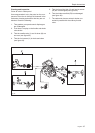
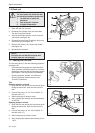
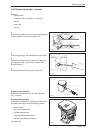
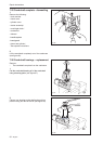
3. Dismantle the springs on the tank unit with the
help of a 5 mm allen key (tool 502 50 18-01)
(see gure 50).
Cleaning and inspection
Clean and inspect all parts.
Assembly
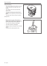
1. Assemble the springs on the cylinder with the
help of a 5 mm allen key (tool 502 50 18-01).
Note! Springs with a greater resistance are av-
ailable, but should only be used together with
a longer bar. See illustrated part list for spare
part number.
2. Assemble the following parts:
• Tank unit and handle.
• Cylinder cover. See the Operator's Manual.
• Bar and chain. See the Operator's Manual.
Fig 48
Fig 49
Fig 50