


12 Operation
5WPMAN0100 (Rev. 5/2/2008)
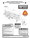
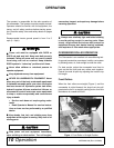
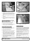
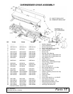
Figure 5. Top Link Attached to Overseeder
2. Attach the tractor’s top link to the upper mast of the
overseeder. Secure with high-strength top link pin
and retaining pin provided with the tractor. See Fig-
ure 5.
3. Adjust top link as needed to level the overseeder
fore and aft.
4. Adjust the lower lift arm anti-sway device to pre-
vent the overseeder from excessive side-to-side
movement.
QUICK HITCH BUSHING KIT (OPTIONAL)
NOTE: An optional quick hitch bushing kit
(5WP1002019) is available through your dealer.
1. Use bushing kit when using a quick hitch.
2. Place .94 x 1.44 x 2.44 bushings (5WP1001702)
over mounting pins and secure into position.
ADJUST FRONT ROLLER ANGLE
1. Position tractor and overseeder on a level surface.
2. Raise overseeder slightly off the ground.
3. Stop engine and set parking brake.
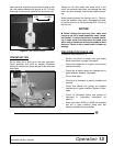
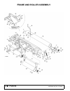
4. Remove klik pin (21), lock pin (15), and lock
assembly (5), Figure 6, from front of overseeder.
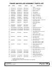
5. Raise the adjustment handle (16), Figure 7, and
pivot it to the next adjustment hole. Move handle
rearward; front roller will start to angle. Continue
this process until front roller has the desired angle.
6. Install lock assembly (5), lock pin (15), and klik pin
(21) to secure front roller into position.
7. Reverse this procedure to move front roller back
into normal position.
Figure 6. Lock Pin and Lock Assembly
Figure 7. Adjustment Handle
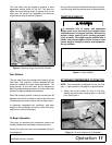
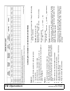
SEEDING OPERATION
Tractor speed and seed flow settings are critical for
proper seed population. Check the seed control chart,
located on the inside of the seedbox lid (see page 14).
Adjust the flow control handle (Figure 8) as needed for
the seed being used and the population desired.
Tractor speed, normally 2-5 mph (3-8 kph), should be
established so that uniform seed incorporation occurs
with the action of the rollers.
The seed chart is based on a standard sprocket config-
uration. Any adjustments to this ratio will result in a
change to the flow rate, as described in the chart.
NOTE: The seed control chart should be used as a
general guide only.
Before seeding an area, check the attitude of the
seeder and adjust the top link so that the front and rear
Top Link Pin
DP2
15
DP3
5
21
16
DP4