


Operation 11
5WPMAN0100 (Rev. 5/2/2008)
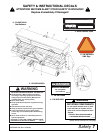
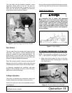
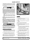
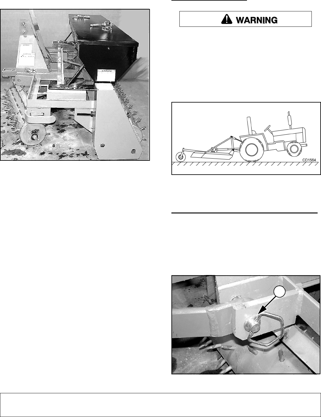
The front rollers can be angled to promote a more
aggressive tearing action of the turf. The more the
angle, the more tearing action is applied by the front
roller pins. For severe turf conditions, the maximum
angle position may be desired (Figure 2).
Figure 2. Maximum Angle Front Roller Position
Rear Rollers
The rear roller firms and presses soil kicked up by the
front roller. This creates a uniform seedbed with the
loose soil needed for proper seed germination. The
spring tension on the rear roller can be adjusted to
deliver the desired down pressure and roller action and
achieve the desired seedbed appearance.
When the situation permits, making a second pass 90
degrees to the first is an effective way for the roller pins
to penetrate areas where uneven soil conditions exist.
In extremely compacted soil conditions, add extra
weight to the overseeder to help the roller pins pene-
trate the turf and soil sufficiently.
To Begin Operation
The power for operating the overseeder comes from
contact between the overseeder rollers and the turf.
Know how to stop the tractor and overseeder quickly in
an emergency.
Survey the area to be worked and remove any obstruc-
tions that may affect the performance of the equipment.
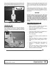
TRACTOR STABILITY
A minimum 20% of tractor and equipment
weight must be on the tractor front wheels when
attachments are in transport position. Without this
weight, tractor could tip over, causing personal
injury or death. The weight may be attained with a
loader, front wheel weights, ballast in tires or front
tractor weights. Weigh the tractor and equipment.
Do not estimate.
Figure 3. Tractor Stability
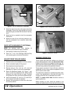
ATTACHING OVERSEEDER TO TRACTOR
NOTE: This overseeder is designed for use on Cate-
gory 1, 3-point tractors. See page 4 for specifications.
1. Attach the tractor’s lower lift arms to the over-
seeder and secure with mounting pins (11) and klik
pins. See Figure 4.
Figure 4. Lift Arms Attached to Overseeder
DP6
11
DP1