


ASSEMBLY
10
MTF-0410104L
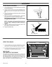
UPPER HANDLE ASSEMBLY
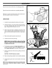
1. Cut tie holding shift rod to lower handle and move shifter
to the neutral position.
2. Loosen, but do not remove the screws, flatwashers, lock-
washers and hex nuts in the upper holes of the lower han-
dle.
3. Remove the fasteners from the lower holes of the lower
handle See Figure 5.
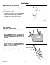
4. Raise upper handle into operating position. Upper han-
dle should be to the outside of the lower handle.
NOTE: Make sure the cables are not caught between
the upper and lower handle.
NOTE: If the cables have become disconnected form
the drive levers, reinstall the cables as shown in
Figure 6.
5. Install the fasteners that were removed in step 3. DO
NOT tighten until all bolts are in place.
6. Tighten all handle bolts.
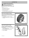
Figure 5
Nut
Flatwasher
Bolt
Lockwasher
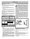
Figure 6
Lever
“Z” Fitting
Control Cable
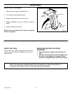
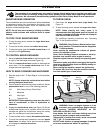
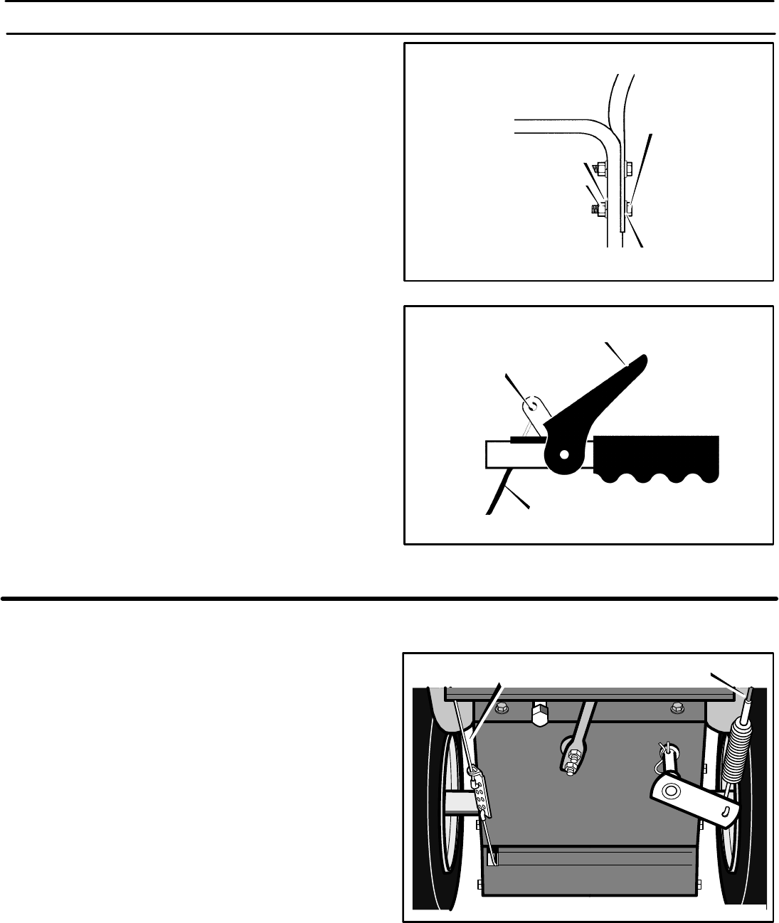
CHECK THE CABLES
1. If control cables have become unattached from motor
mount frame, reconnect cables as shown in Figure 7.
2. For cable adjustments, see “How To Check And Adjust
The Cables” in the MAINTENANCE section.
HOW TO SET
THE LENGTH OF THE CABLES
The cables were adjusted at the factory and no adjustments
should be necessary. However, after the handles are put in
the operating position, the cables can be too tight or too
loose. If an adjustment is necessary, see “How To Check And
Adjust The Cables” in the MAINTENANCE section.
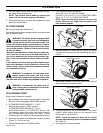
Traction Drive Cable
Auger Drive Cable
Figure 7