


Controls
18 Operator’s Manual
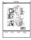
CONTROLS
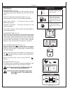
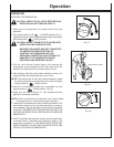
ENGINE SWITCH: (Fig. 15)
The engine switch is designed for easy operation with the
interlocking mechanism between the fuel valve and the
choke.
OUTPUT LAMP AND OVERLOAD LAMP:
(Fig. 16)
These lamps are turned on in the following conditions:
Output Lamp (Green) --- The lamp is turned on while
generating properly.
Overload Lamp (Red) --- The lamp is turned on in the
overload condition.
If the lamp is turned on, stop and start the engine again to
resume the operation.
OIL SEN
SOR LAMP: (Fig. 17)
When the level of the engine oil falls below the prescribed
value, the alarm lamp lights up and the engine stops
automatically. When the engine stops due to oil shortage,
it can not be started anymore even by pulling the start kn
ob
(just the alarm lamp flickers). In such a case, replenish
engine oil. See “Pre-Operation; Engine Oil” on page 21.
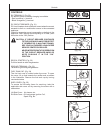
AUTO POWER SAVE SWITCH: (Fig. 18)
With the switch in the “ “ marking position, the engine
speed is reduced automatically when no load is applied,
while the engine speed is automatically increased when
the load is applied.
When using in the heavy load condition, set the switch into
the “ “ marking position to maintain the engine RPM at
the rated setting.
When using DC power, turn the switch into the “ ”
position.
AC RECEPTA
CLES: (Fig. 19)
AC electric power is available through this receptacle. Use
a grounding type plug as shown on page 26, Table 1.
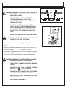
WARNING: DO NOT PUT FOREIGN OBJECTS
INTO THE PLUG RECEPTACLE.
CAUTION: DO NOT PLUG MORE THAN TWO
APPLIANCES INTO THE GENERATOR
AT A TIME.
ENGINE SWITCHES
CHOKE To start the engine, turn the
knob to the position. (Choke
valve is closed.)
RUN Keep the knob in this
position after the engine
starts. (The engine can be
started with the knob at the
position when the engine is
warm.
STOP To stop the engine, return
the knob to the position.
(The fuel cock is closed as
well.)
(Fig. 15)
(Fig. 16)
(Fig. 17)
(Fig. 19)
OUT
PUT
OVER
LOAD
(Fig. 18)