


30 Assembly
5WPMAN0879 (3/18/2011)
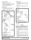
Torque Caster Arms
1. Place mower on a hard level surface.
2. Loosen cap screws and lock nuts on all four caster
wheel arms. This allows clearance in the caster
wheel assemblies to be equalized.
3. Torque all cap screws and nuts to 85 lbs-ft.
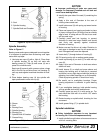
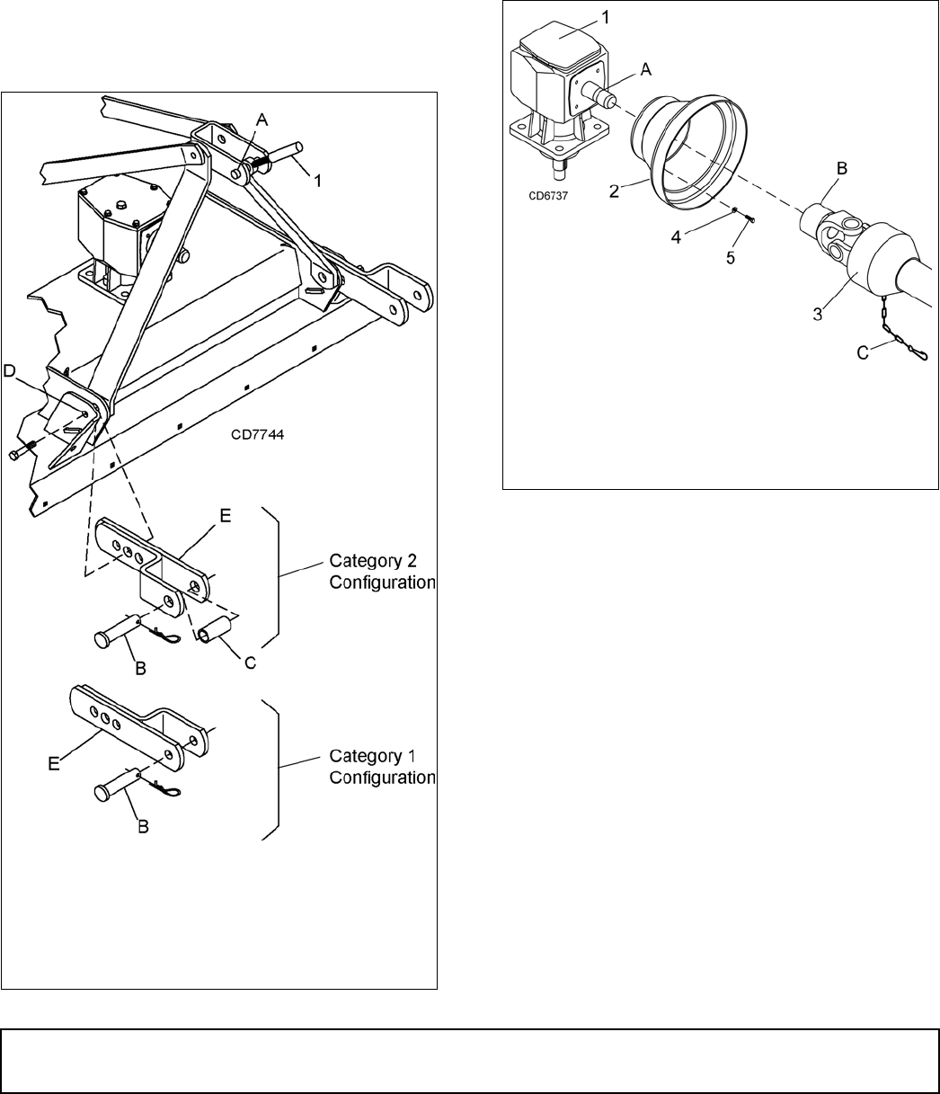
Install Hitch Arms
1. Remove cap screws, lock nuts and hitch arms (E)
from lower hitch arm attachment point (D).
2. Position arms according to Figure 29 and replace
hardware.
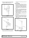
Figure 29. Hitch Arm Installation
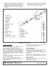
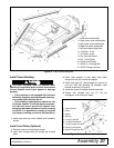
Install Driveshaft
1. Pull locking collar (B) back and, at the same time,
push driveline onto gearbox shaft until locking
device engages.
2. Rotate PTO hanger forward. Rest driveline on PTO
hanger.
3. If so equipped, hook anti-rotation chain (C) on
shield (2).
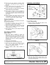
Figure 30. Driveshaft Installation
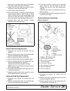
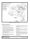
Fill Gearbox
NOTICE
■ Gearbox is not filled at the factory. Prior to
delivery, make sure each gearbox is filled half-full
with 80W or 90W API GL-4 or GL-5 gear lube.
1. Make sure vent plug hole is clear. Fill gearbox half-
full with high quality gear oil that has a viscosity
index of 80W or 90W and an API service rating of
GL-4 or GL-5.
2. Fill gearbox until oil runs out the side plug on
gearbox.
3. Pour in one pint of gear lube, wait five minutes and
add additional gear lube until it just comes out of
side hole.
4. Allow an additional five minutes for the lube to flow
through bearings, then check to make sure oil level
is at bottom of side hole. Replace side plug. Install
vent plug.
1. Tractor top link
A. Mower top link attachment point
B. Mower hitch pin
C. Category 2 sleeve
D. Lower hitch arm attachment point
E. Mower hitch arm
A. Gearbox input shaft
B. Locking collar
C. Anti-rotation chain
1. Gearbox
2. Shield
3. Driveline
4. Washer, flat standard 5/16
5. Screw, HHCS 8 mm x 1.25P x 16 mm