


Operation 11
5WPMAN0879 (3/18/2011)
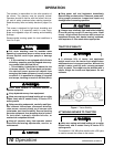
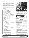
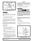
Refer to Figure 2
1. For Category 1 hitch, position mower hitch arms
(E) with offset toward center of mower. For
Category 2 hitch, position mower hitch arms (E)
with offset toward outside of mower.
2. Attach the mower hitch pins (B) to lower tractor lift
arms and secure.
3. Attach tractor top link (1) to mower top link bracket
attachment point A. Connect driveline to tractor
PTO shaft.
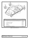
Figure 2. Attachment Points
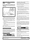
Figure 3. Attaching Mower to Tractor
4. Attach tether chain to tractor drawbar if drive
equipped with chain, (Figure 3).
5. Adjust the tractor lower 3-point arm anti-sway
devices to prevent mower from swinging side to
side during transport.
CUTTING HEIGHT ADJUSTMENT
Keep all persons away from operator control
area while performing adjustments, service, or
maintenance.
NOTICE
■ Avoid low cutting heights. Striking the ground
with blades produces one of the most damaging
shock loads a mower can encounter. Allowing
blades to contact ground repeatedly will cause
damage to mower and drive.
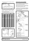
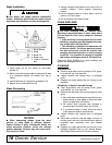
1. Level mower from side to side. Check by
measuring from mower frame to the ground at
each deck rail.
2. Verify that the same amount of spacers are under
all caster arms.
3. Loosen cap screws that attach caster arm
assembly to deck.
4. Set mower on the ground.
5. Retighten cap screws. This equalizes the
clearance in the bolt holes.
6. Adjust front of mower level with or slightly lower
than the rear to obtain best mowing results. See
Figure 4.
7. Control cutting height by adjusting front and rear
caster wheels.
8. To raise rear of mower, move caster adjustment
spacers under rear caster arms. See Figure 6.
1. Tractor top link
A. Mower top link attachment point
B. Mower hitch pin
C. Category 2 sleeve
D. Lower hitch arm attachment point
E. Mower hitch arm
CM906
Tether Chain