


32 Assembly
5WPMAN0511 (Rev. 5/9/2008)
I
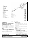
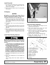
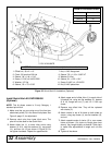
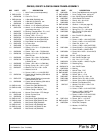
Figure 35. Quick Hitch Kit Installation (Optional)
Install Quick Hitch Kit 5WD1005400
(Optional)
NOTE: This kit allows mower to fit only Category 1
standard quick hitch.
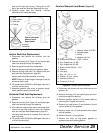
1. Make sure that you are using one of the front two
attachment points (D) in the lower hitch plates. See
Figure 6, page 12, for adjustment.
2. Remove clevis pins from lower hitch arms. The
pins will not be used for the Quick Hitch.
3. Attach offset link (1) to lower hitch clevis using
sleeves (3 & 8), two flat washers (9), cap screw
(11), and hex nut (12) as shown in Figure 35. Do
not tighten hardware. Repeat for opposite side.
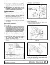
4. Attach upper end of offset links (1) to each side of
U-bracket link, using two flat washers (5), sleeves
(6 & 10), flange lock nut (7), and 1/2 x 4-3/4 cap
screw.
5. Remove rear offset links. They will be replaced
with chains (2).
6. Attach chains to top of A-frame on both sides as
shown, using cap screw (4), two flat washers (5),
and nut.
7. Attach opposite ends of chains (2) to rear mower
frame as shown. Cut chains to length (see chart
above). Vary length slightly as desired. Twist chain
to make finite adjustments in length until unit lifts
level.
8. Tighten all hardware.
1. Offset link, .38 x 2 x 15"
2. Chain, 3/8 proof coil 38-link
3. Sleeve, .94 x 1.44 x 1.94"
4. Screw, 1/2 NC x 6 HHCS GR5
5. Washer, 1/2" flat
6. Sleeve, .50 x .75 x 3.38"
7. Nut, 1/2 NC flange lock
8. Sleeve, 7/8 x 1-1/8 x 19/32" HT
9. Washer, 3/4 flat
10. Sleeve, .81 x 1.25 x 1.81"
11. Screw, 3/4 NC x 4-1/2 HHCS
12. Nut, 3/4 NC plated hex
CHAIN CUT-TO-LENGTH CHART
Model Dimension “A”
GM1060 40"
GM1072 45"
GM1084 50"
NOTE:This kit is used on other models. Use only the hardware listed below.
(Rev. 10/18/2012)