


12 Operation
5WPMAN0511 (Rev. 7/18/2008)
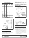
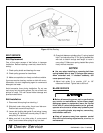
Figure 5. Height Adjustment with Caster Arm Spacers
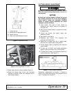
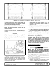
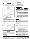
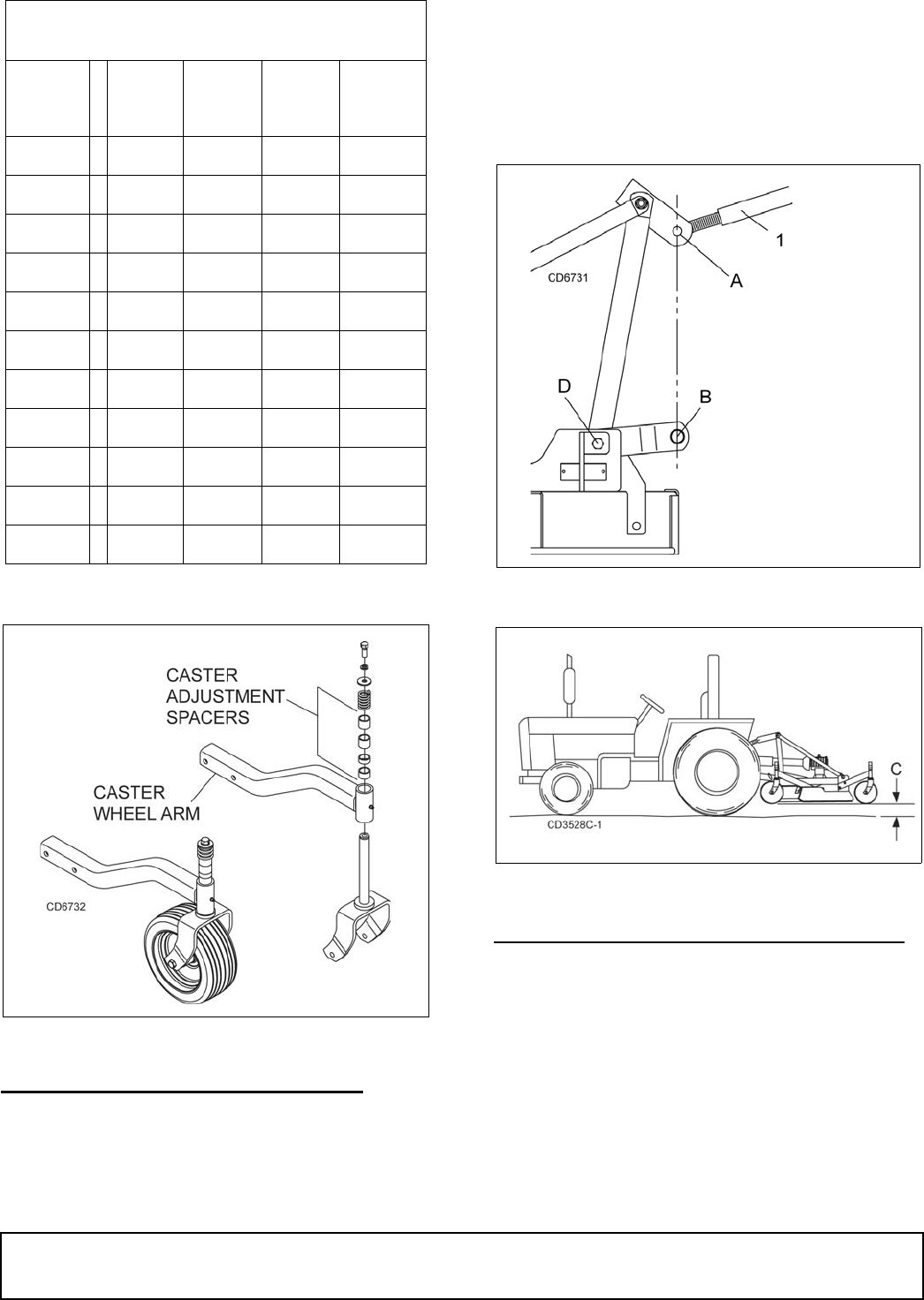
TRACTOR TOP LINK ADJUSTMENT
When the cutting height is set, adjust tractor top link
until mower top link attachment point (A) is aligned ver-
tically with mower hitch pin (B), Figure 6.
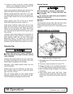
Adjust tractor top link so mower is level between caster
wheel and ground (dimension C), Figure 7. This will
allow the mower to follow ground contour.
The mower has three lower hitch plate attachment
points (D), Figure 6. It may be necessary to change the
mower hitch plate attachment point to obtain proper tire
clearance and/or lift height.
Figure 6. Top Link Adjustment
Figure 7. Caster Wheel Distance
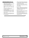
FRONT CASTER ARM CONFIGURATION
For GM1060 & GM1072 only
The front casters can be set in two positions. Figure 8
shows the two possible configurations for the GM1060
and GM1072 front caster arms.
● The inner position allows the outside edge of the
mower to be used for trimming under shrubs or
fences.
● The outer position provides the most clearance for
rear tractor tire interference.
SPACERS REQUIRED UNDER
CASTER ARM PIVOT TUBE
Cut
Height
1/2"
Spacer
3/4"
Spacer
1"
Spacer
1-1/4"
*Spacer
(Spring)
1"
1-1/2" 1
2" 1
2-1/2" 11
3" 2
3-1/2" 12
4" *111
4-1/4" 112
4-1/2" *1 1 1 1
5" *121
5-1/2" *1 1 2 1
* GM1060 and GM1072 only
1. Tractor top link
A. Mower top link
attachment point
B. Mower hitch pin
D. Lower hitch plate
attachment point