


26 Dealer Service
5WPMAN0242 (Rev. 7/21/2008)
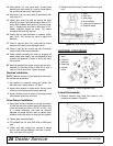
13. Slide spacer (12) over input shaft (3) and press
bearing onto input shaft (3), using a round tube of
the correct diameter and a hand press.
14. Slide shim (13) over input shaft (3) and secure with
snap ring (10).
15. Check input shaft end float by moving the input
shaft (3) by hand. If end float is higher than 0.012",
insert shim between input shaft (3) and rear bear-
ing (7). Repeat until end float is less than 0.012".
Check rotational torque by hand. The torque
should be less than 2.2 lbs-inch.
16. Check that the gear backlash is between 0.006"
and 0.016". You should not have to adjust the
backlash.
17. Press in input oil seal (19), using tube of correct
diameter. Be careful not to damage seal lip.
18. Press oil cap (20) on to cover the rear of housing,
using a tube of the correct diameter.
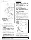
19. Check gearbox housing for leaks by plugging all
holes except one. Apply 4 psi compressed air and
immerse the gearbox in water to verify that there
are no leaks.
20. Remove gearbox from water and dry off with com-
pressed air. Add SAE 80W or 90W EP oil until it
runs out of side level hole. Tighten all plugs.
Gearbox Installation
NOTE: Gearbox is heavy: do not attempt to move with-
out mechanical assistance.
1. Set gearbox on gearbox stand and fasten with
bolts and nuts. Torque bolts to 175 lbs-ft.
2. Attach drive sheave to output shaft. Secure using
castle nut and hardware previously removed.
3. Attach Gearbox stand to mower using cap screws
and washers previously removed.
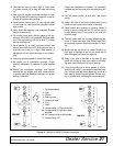
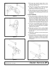
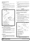
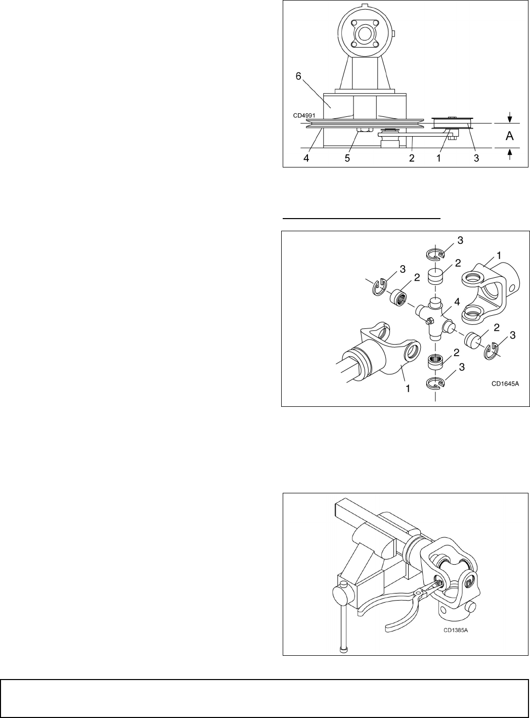
Drive Sheave Installation
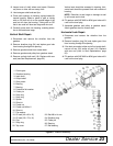
1. When gear stand is installed on mower, dimension
A (from the top of the mower deck to the center line
of the drive pulley) must be 1-27/32" (±1/32"). This
is a critical dimension and must be carefully
adjusted for proper belt life. Add or subtract shim
washers under idler pulley to align with drive pulley.
2. Tighten gear stand hardware.
3. Fill gearbox half full with SAE 80W or 90W gear
lube.
4. Check level after waiting five minutes to permit
lube to work through bearings. Add lube, if neces-
sary, until gearbox is half full.
5. Replace driveline shield. Attach driveline to gear-
box.
Figure 20. Drive Sheave Installation
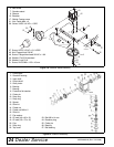
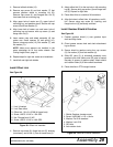
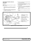
UNIVERSAL JOINT REPAIR
Figure 21. U-Joint Exploded View
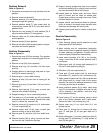
U-Joint Disassembly
1. Remove external snap rings from yokes in four
locations as shown in Figure 22.
Figure 22
1. Shim
2. Idler arm
3. Idler pulley
4. Drive sheave
5. Castle nut & cotter pin
6. Gearbox stand
1. Yoke
2. Cup and
bearings
3. Snap ring
4. Journal
cross