


20 Dealer Service
5WPMAN0242 (Rev. 7/21/2008)
DEALER SERVICE
The information in this section is written for dealer ser-
vice personnel. The repair described here requires
special skills and tools. If your shop is not properly
equipped or your mechanics are not properly trained in
this type of repair, you may be time and money ahead
to replace complete assemblies.
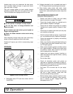
Before working underneath, read manual
instructions, securely block up, and check stability.
Secure blocking prevents equipment from drop-
ping due to hydraulic leak down, hydraulic system
failure, or mechanical component failure.
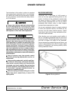
Keep all persons away from operator control
area while performing adjustments, service, or
maintenance.
Always wear relatively tight and belted clothing
to avoid entanglement in moving parts. Wear
sturdy, rough-soled work shoes and protective
equipment for eyes, hair, hands, hearing, and head;
and respirator or filter mask where appropriate.
BLADE SPINDLE SERVICE
Spindle repair requires special skills and tools. If your
shop is not properly equipped or your mechanics are
not trained in this type of repair, you may be time and
money ahead to use a new spindle assembly.
Permatex
®
3D Aviation Form-A-Gasket or equivalent is
recommended as a sealant.
Spindle Removal
1. Remove belt shield.
2. Remove blade from spindle. See Blade Removal,
page 16.
3. Remove belt from pulleys.
4. Remove cap screw and flat washer from top of
spindle assembly
5. Disassemble split taper bushing (located on top of
pulley) by removing the two cap screws and insert-
ing them into the threaded holes in bushing flange.
Tighten cap screws alternately to remove split
taper bushing.
6. Remove pulley.
7. Remove grease fitting extension.
8. Remove the cap screws attaching spindle to
mower frame and remove spindle.
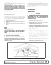
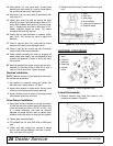
Spindle Repair Tips
As a reference point, the top of spindle housing is the
short portion.
To minimize wear, bearing cups, cones and sleeves are
press fit to shaft and will require a press or similar
device for removal.
When disassembling, support housing casting to pre-
vent damage.
Remove bearing cups by placing a punch in housing
slots and drive cup out. Alternate punch positions from
side to side. Use care to prevent housing damage.
Bore-tite
®
sealant is used on the outer diameter of the
seals. Substitute seals may not meet original equip-
ment specifications and could cause leakage.
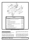
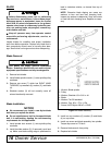
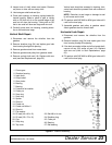
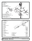
Spindle Disassembly
Refer to Figure 14.
1. Support spindle in a press and push shaft (7) down
through housing (5).
2. Remove seals from housing.
3. Remove bearing cups by placing a punch in hous-
ing slots and drive cup out. Alternate punch posi-
tions from side to side. Use care to prevent
housing damage.
4. Remove bearing cone (4) from shaft (7).
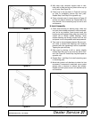
Spindle Assembly
Refer to Figure 14.
NOTICE
■ Bearing adjustment is set by pressing sleeve
against bearing cone until proper adjustment is
attained.
■ Improper positioning of seals can cause seal
failure.
1. Bearing cups and cones are designed to work
together. It is important to position them so bearing
cone taper mates with bearing cup taper.
CAUTION