


Dealer Service 25
5WPMAN0242 (Rev. 7/21/2008)
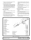
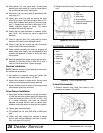
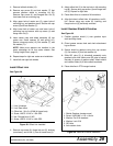
Gearbox Removal
Refer to Figure 18.
1. Disconnect and remove the rear driveline from the
gearbox.
2. Remove center belt shield (2).
3. Remove breather (10) and siphon gear lube from
housing through this opening.
4. Remove gearbox stand (7) from mower deck by
removing cap screws (36 & 37) from each side of
gearbox stand.
5. Remove four cap screws (51) and washers (50 &
49) and remove shield (17) from gearbox.
6. Remove castle nut (31) and hardware from output
shaft of gearbox.
7. Remove sheave (9) from gearbox.
8. Remove four bolts (48) that attach gearbox to gear-
box stand and remove gearbox.
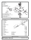
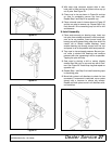
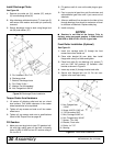
Gearbox Disassembly
Refer to Figure 19.
1. Remove top cover (22) from housing. Turn gearbox
upside down and pour out remaining gear oil from
gearbox.
2. Remove oil cap (20) (to be replaced).
3. Remove snap ring (10) and shim (13) from input
shaft (3).
4. Support gearbox in hand press and push on input
shaft (3) to remove bearing (7).
5. Remove gear (1) from inside housing.
6. Remove oil seal (19) from front of housing (to be
replaced).
7. Remove snap ring (10) and shim (13) from front of
housing (2).
8. Remove input bearing (7) by using a punch and
hammer from outside of housing.
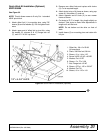
9. Support housing in vise in a horizontal position.
10. The castle nut (15) and cotter pin (25) are already
removed with the drive sheave. Remove the snap
ring (21), washer (8), and seal (18).
11. Remove cotter pin (9), castle nut (14), and washer
(17) from output shaft (4).
12. Remove output shaft (4) by using a punch and
hammer and tap on top to drive down.
13. Remove gear (5) and shim (16) from inside hous-
ing.
14. Remove bearing (26) by using a punch and ham-
mer from the top, outside the housing.
15. Support housing upside down (top cover surface)
and remove bearing (6) by using a punch and ham-
mer from the bottom side of the housing.
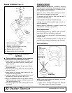
16. Inspect gears for broken teeth and wear. Some
wear is normal and will show on loaded side.
Forged gear surfaces are rough when new. Check
that wear pattern is smooth.
17. Inspect vertical and horizontal shafts for grooves,
nicks, or bumps in the areas where the seals seat.
Resurface any damage with emery cloth.
18. Inspect housing and caps for cracks or other dam-
age.
Gearbox Reassembly
Refer to Figure 19.
1. Clean housing, paying specific attention to areas
where gaskets will be installed.
2. Wash housing and all components thoroughly.
Select a clean area for gearbox assembly. Replace
all seals, bearings, and gaskets. All parts must be
clean and lightly oiled before reassembling.
3. Insert output bearings (6 & 26) in the housing,
using a round tube of the correct diameter and a
hand press.
4. Slide output shaft (4) through both bearings (6 &
26) until it rests against bearing (6).
5. Slide shim (16) over output shaft (4).
6. Press gear (5) onto output shaft (4) and secure
with washer (17), castle nut (14), and cotter pin (9).
7. Apply grease to lower seal lips (18) and press seal
over output shaft (4), using a tube of the correct
diameter. Be sure not to damage the seal lip. Press
in housing so that seal is recessed.
8. Insert protective washer (8) by hand. Install snap
ring (21) and position it together with dual lip seal
(18) by pressing it into position. Verify that snap
ring is seated correctly.
9. Press bearing (7) into the housing, using a round
tube of the correct diameter and a hand press.
Secure with shim (13) and snap ring (10).
10. Secure snap ring (11) on input shaft (3) if not
already secure.
11. Place gear (1) through top of housing and align
gear (1) and gear (5) so that gear teeth are a
match.
12. While holding gear (1) in place, slide input shaft (3)
through gear (1) and bearing (7). Align splines on
shaft (3) and gear (1).