


34 Assembly
5WPMAN0183 (Rev. 4/25/2008)
ASSEMBLY INSTRUCTIONS
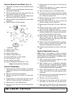
DEALER SET-UP INSTRUCTIONS
The mower is shipped mostly assembled but requires
dealer set-up. The Frontier dealer should deliver the
mower to the owner completely assembled, lubricated,
and adjusted for normal conditions.
Recommended torque values for hardware are located
on page 57.
Complete the Dealer Check Lists on page 36 when
assembly is complete.
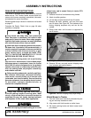
Keep hands and body away from pressurized
lines. Use paper or cardboard, not hands or other
body parts to check for leaks. Wear safety goggles.
Hydraulic fluid under pressure can easily penetrate
skin and will cause serious injury or death.
Make sure that all operating and service person-
nel know that if hydraulic fluid penetrates skin, it
must be surgically removed as soon as possible by
a doctor familiar with this form of injury or gan-
grene, serious injury, or death will result. CON-
TACT A PHYSICIAN IMMEDIATELY IF FLUID
ENTERS SKIN OR EYES. DO NOT DELAY.
Before dismounting power unit or performing
any service or maintenance, follow these steps:
disengage power to equipment, lower the 3-point
hitch and all raised components to the ground,
operate valve levers to release any hydraulic pres-
sure, set parking brake, stop engine, remove key,
and unfasten seat belt.
Before working underneath, carefully read Oper-
ator’s Manual instructions, disconnect driveline,
raise mower, securely block up all corners with
jackstands, and check stability. Secure blocking
prevents equipment from dropping due to hydrau-
lic leak down, hydraulic system failures, or
mechanical component failures.
Always wear relatively tight and belted clothing
to avoid getting caught in moving parts. Wear
sturdy, rough-soled work shoes and protective
equipment for eyes, hair, hands, hearing, and head;
and respirator or filter mask where appropriate.
Make sure spring-activated locking pin or collar
slides freely and is seated firmly in tractor PTO
spline groove.
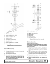
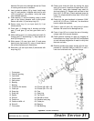
1. Remove front drive from between wing frames.
2. Attach to splitter gearbox.
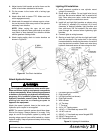
3. Lift rear deck to take tension off rear lift chains.
4. Remove 3/8 bolts, washers, and nuts from both
rear lift chains. See Figure 28. This hardware is for
factory shipping purposes only and can be dis-
carded.
5. Gently lower deck until the deck is supported by
the lift chains.
Figure 28. Remove Shipping Hardware
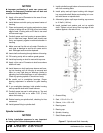
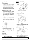
6. Remove 5/8 lock nuts and remove shipping strap
from between right and left decks.
Figure 29. Remove Shipping Strap (Right Wing)
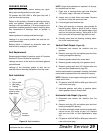
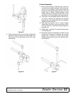
Attach Mower to Tractor
1. Park the mower on a hard level surfaced with park-
ing jack securely fastened to trailer.
2. Align tractor with hitch bracket on trailer frame.
3. Set tractor parking brake and block mower trans-
port wheels.
CAUTION
Remove Hardware
Remove 5/8 Lock nut