


Operation 15
5WPMAN0183 (Rev. 4/25/2008)
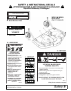
5. Retighten cap screws. This equalizes the clear-
ance in the bolt holes.
6. Best mowing results will be obtained with front of
mower level with, or slightly lower than, the rear.
7. Cutting height is controlled with front and rear
caster wheel adjustment.
8. To raise rear of mower, move caster adjustment
spacers under caster arms.
9. To raise front of mower, move spacers under front
caster wheel arms.
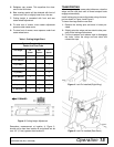
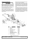
Figure 3. Cutting Height Adjustment
Remember, measurement at location A, Figure 3,
should not be less than location B and should not be
over 1/2" (13 mm) greater than location B.
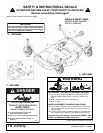
TRANSPORTING
When transporting the mower short distances, raise the
wings and the rear deck until all three transport locks
engage automatically.
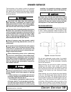
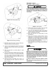
Install locking pins to secure the mower wings for trans-
port as shown in Figure 4 and Figure 5.
To lower the wings and the rear deck:
1. Remove the locking pins and store in holes pro-
vided.
2. Slightly raise the wings and rear deck to take pres-
sure off the locking mechanisms.
3. Pull the transport lock release rope to disengage
the locks. Lower the wings and rear deck and
release the rope.
Figure 4. Lock Pin Installed (Right Wing)
Figure 5. Lock Pin Installed (Rear Deck)
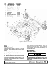
Table 1: Cutting Height Chart
Spacers Required Under
Caster Arm Pivot Tube
Cut Height 1/2"
Spacer
3/4"
Spacer
1"
Spacer
1" (25 mm)
1-1/2" (38 mm)
1
2" (51 mm)
1
2-1/2" (64 mm)
11
3" (76 mm)
2
3-1/2" (89 mm)
12
4" (102 mm)
121
4-1/2" (114 mm)
22
5" (127 mm)
122