


32 Dealer Service
5WPMAN0183 (Rev. 4/25/2008)
Gearbox Installation
NOTE: Gearbox is heavy: do not attempt to move with-
out mechanical assistance.
1. Set gearbox on gearbox stand and fasten with
bolts and nuts. Torque bolts to 175 lbs.-ft. (237 N-
m).
2. Attach drive sheave to output shaft. Secure using
castle nut and hardware previously removed.
3. Attach Gearbox stand to mower using four flanged
lock nuts.
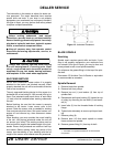
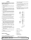
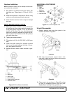
DRIVE SHEAVE INSTALLATION
1. When gear stand is installed on mower, dimension
A (from the top of the mower deck to the center line
of the drive pulley) must be 2-7/16" (61.913 mm)
[±1/32" (±0.794 mm)]. This is a critical dimension
and must be carefully adjusted for proper belt life.
Add or subtract shim washers under idler pulley to
align with drive pulley.
2. Tighten gear stand hardware.
3. Fill gearbox half full with SAE 80W or 90W gear
lube.
4. Check level after waiting five minutes to permit
lube to work through bearings. Add lube, if neces-
sary, until gearbox is half full.
5. Replace driveline shield. Attach driveline to gear-
box.
Figure 21. Drive Sheave Installation
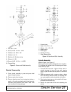
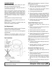
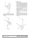
UNIVERSAL JOINT REPAIR
Figure 22. U-Joint Exploded View
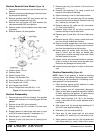
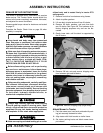
U-Joint Disassembly
1. Remove external snap rings from yokes in four
locations as shown in Figure 23.
Figure 23
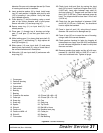
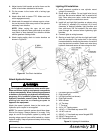
2. With snap rings removed, support drive in vise,
hold yoke in hand and tap on yoke to drive cup up
out of yoke. See Figure 24.
Figure 24
3. Clamp cup in vise as shown in Figure 25 and tap
on yoke to completely remove cup from yoke.
Repeat Step 2 and Step 3 for opposite cup.
1. Shim
2. Idler Arm
3. Idler Pulley
4. Drive Sheave
5. Castle nut & Cotter pin
6. Gearbox Stand
1. Yoke
2. Cup and
bearings
3. Snap ring
4. Journal cross
(Rev. 7/9/2008)