


Assembly
1. Finish removing the crate from around the
machine.
2. Remove the bolts holding the machineto the
skid.
3. Carefully clean all rust protected surfaceswith a
mild solvent or kerosene and a soft rag. Do not
use lacquer thinner, paint thinner, or gasoline.
These will damage painted surfaces.
4. Coat all machined surfaces with a very light film
of oil to inhibit rust.
5. Carefully move the shear, brake, and roll to a
work bench or stand. Machine location must
allow free access on all sides.
6. Bolt the machine to a stand or a workbench. If
using a stand, the stand must be boltedto the
floor. If using a work bench, the bench must be
bolted to the floor.
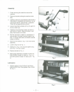
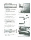
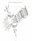
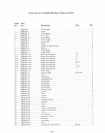
7. Remove one handle (A, Fig. 1)from the handle
assembly.
8. Loosen wing lock (B, Fig. 1).
9. Slide bar (C, Fig. 1) into hub and tighten wing
lock (Fig. 1)to hold in place.
10. Replace handle (B. Fig. 1).
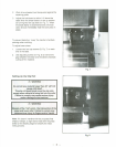
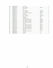
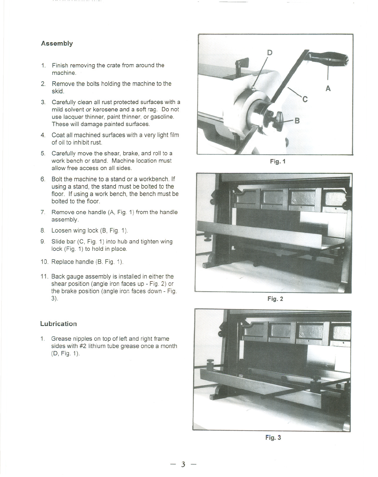
11. Back gauge assembly is installed in either the
shear position (angle iron faces up - Fig. 2) or
the brake position (angle iron faces down - Fig.
3).
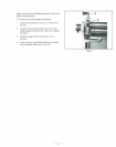
Lubrication
1. Grease nipples on top of left and rightframe
sides with #2 lithium tube grease once a month
(0, Fig. 1).
- 3 -
A
t
Fig. 1
Fig. 2
Fig. 3